Chapter 5 Connecting the Management Interfaces and Performing Initial System Configuration
Connecting the Management Interface
Cabling the Management Port
The SCE 2000 has two management ports, labeled Mng1 and Mng 2.
To cable the management port, complete the following steps:
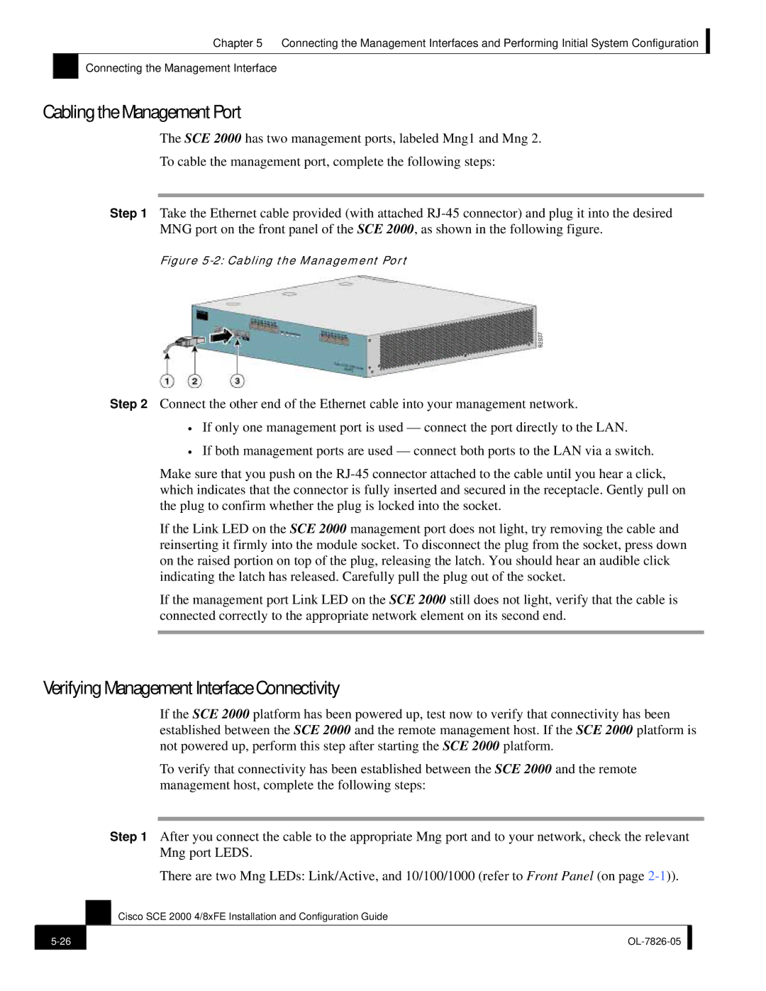
Step 1 Take the Ethernet cable provided (with attached
Figure 5-2: Cabling the Management Port
Step 2 Connect the other end of the Ethernet cable into your management network.
•If only one management port is used — connect the port directly to the LAN.
•If both management ports are used — connect both ports to the LAN via a switch.
Make sure that you push on the
If the Link LED on the SCE 2000 management port does not light, try removing the cable and reinserting it firmly into the module socket. To disconnect the plug from the socket, press down on the raised portion on top of the plug, releasing the latch. You should hear an audible click indicating the latch has released. Carefully pull the plug out of the socket.
If the management port Link LED on the SCE 2000 still does not light, verify that the cable is connected correctly to the appropriate network element on its second end.
Verifying Management Interface Connectivity
If the SCE 2000 platform has been powered up, test now to verify that connectivity has been established between the SCE 2000 and the remote management host. If the SCE 2000 platform is not powered up, perform this step after starting the SCE 2000 platform.
To verify that connectivity has been established between the SCE 2000 and the remote management host, complete the following steps:
Step 1 After you connect the cable to the appropriate Mng port and to your network, check the relevant Mng port LEDS.
There are two Mng LEDs: Link/Active, and 10/100/1000 (refer to Front Panel (on page
Cisco SCE 2000 4/8xFE Installation and Configuration Guide
| ||
|
|
|