Cisco Systems SCE 2000 4/8xFE manual LEDs

Models: SCE 2000 4/8xFE

1 131
Download 131 pages 39.66 Kb
Page 48
Image 48
LEDs

Chapter 4 Installation and Maintenance

Power Supply Overview

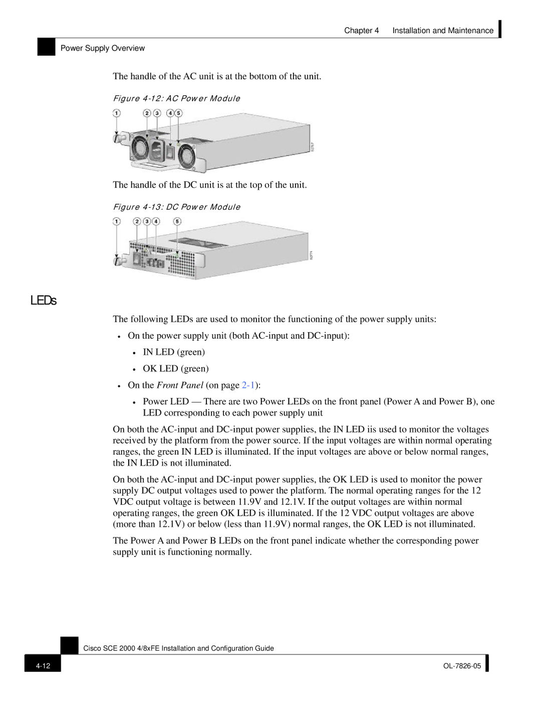
The handle of the AC unit is at the bottom of the unit.

Figure 4-12: AC Power Module

The handle of the DC unit is at the top of the unit.

Figure 4-13: DC Power Module

LEDs

The following LEDs are used to monitor the functioning of the power supply units:

On the power supply unit (both AC-input and DC-input):

IN LED (green)

OK LED (green)

On the Front Panel (on page 2-1):

Power LED — There are two Power LEDs on the front panel (Power A and Power B), one LED corresponding to each power supply unit

On both the AC-input and DC-input power supplies, the IN LED iis used to monitor the voltages received by the platform from the power source. If the input voltages are within normal operating ranges, the green IN LED is illuminated. If the input voltages are above or below normal ranges, the IN LED is not illuminated.

On both the AC-input and DC-input power supplies, the OK LED is used to monitor the power supply DC output voltages used to power the platform. The normal operating ranges for the 12 VDC output voltage is between 11.9V and 12.1V. If the output voltages are within normal operating ranges, the green OK LED is illuminated. If the 12 VDC output voltages are above (more than 12.1V) or below (less than 11.9V) normal ranges, the OK LED is not illuminated.

The Power A and Power B LEDs on the front panel indicate whether the corresponding power supply unit is functioning normally.

Cisco SCE 2000 4/8xFE Installation and Configuration Guide

4-12

OL-7826-05


Page 48
Image 48
Cisco Systems SCE 2000 4/8xFE manual LEDs