•Fan information
•Switch backplane information
LEDs and Sensors Tab
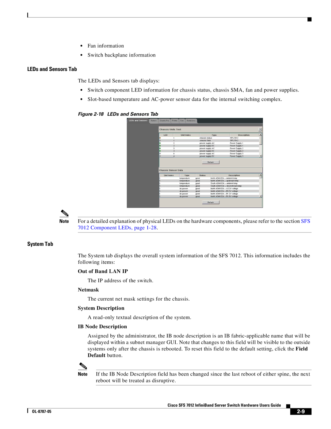
The LEDs and Sensors tab displays:
•Switch component LED information for chassis status, chassis SMA, fan and power supplies.
•
Figure 2-18 LEDs and Sensors Tab
Note For a detailed explanation of physical LEDs on the hardware components, please refer to the section SFS 7012 Component LEDs, page
System Tab
The System tab displays the overall system information of the SFS 7012. This information includes the following items:
Out of Band LAN IP
The IP address of the switch.
Netmask
The current net mask settings for the chassis.
System Description
A
IB Node Description
Assigned by the administrator, the IB node description is an IB
Note If the IB Node Description field has been changed since the last reboot of either spine, the next reboot will be treated as disruptive.
Cisco SFS 7012 InfiniBand Server Switch Hardware Users Guide
|
| ||
|
|
