Figure 2-16 Reboot Screen
Step 2 Select the radio button of the spine(s) to be rebooted, or select the Reboot Entire Chassis radio button to reboot the SFS 7012 chassis and all spines.
Step 3 Click Reboot.
Chassis View Component Information Area
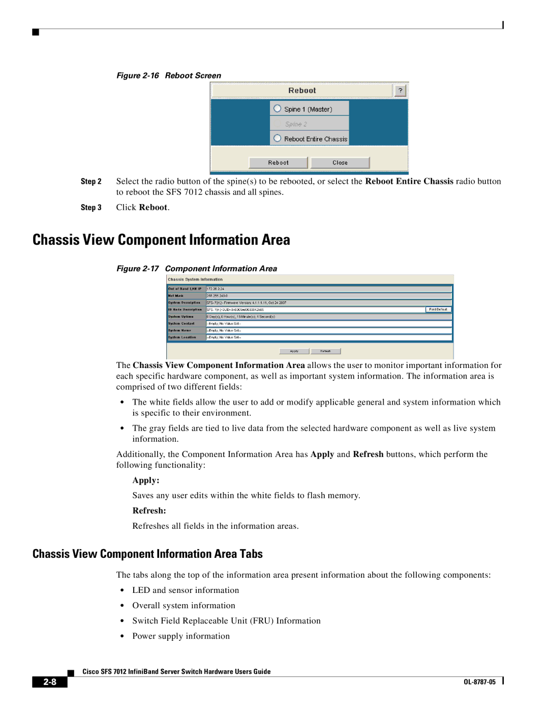
Figure 2-17 Component Information Area
The Chassis View Component Information Area allows the user to monitor important information for each specific hardware component, as well as important system information. The information area is comprised of two different fields:
•The white fields allow the user to add or modify applicable general and system information which is specific to their environment.
•The gray fields are tied to live data from the selected hardware component as well as live system information.
Additionally, the Component Information Area has Apply and Refresh buttons, which perform the following functionality:
Apply:
Saves any user edits within the white fields to flash memory.
Refresh:
Refreshes all fields in the information areas.
Chassis View Component Information Area Tabs
The tabs along the top of the information area present information about the following components:
•LED and sensor information
•Overall system information
•Switch Field Replaceable Unit (FRU) Information
•Power supply information
Cisco SFS 7012 InfiniBand Server Switch Hardware Users Guide
| ||
|