Hardware Overview
Hardware Overview
This section describes the
•Chassis
•Backplane
•Fan module
•Control Module
•Power Supply
•Switching Fabric Module
•Line cards
Chassis
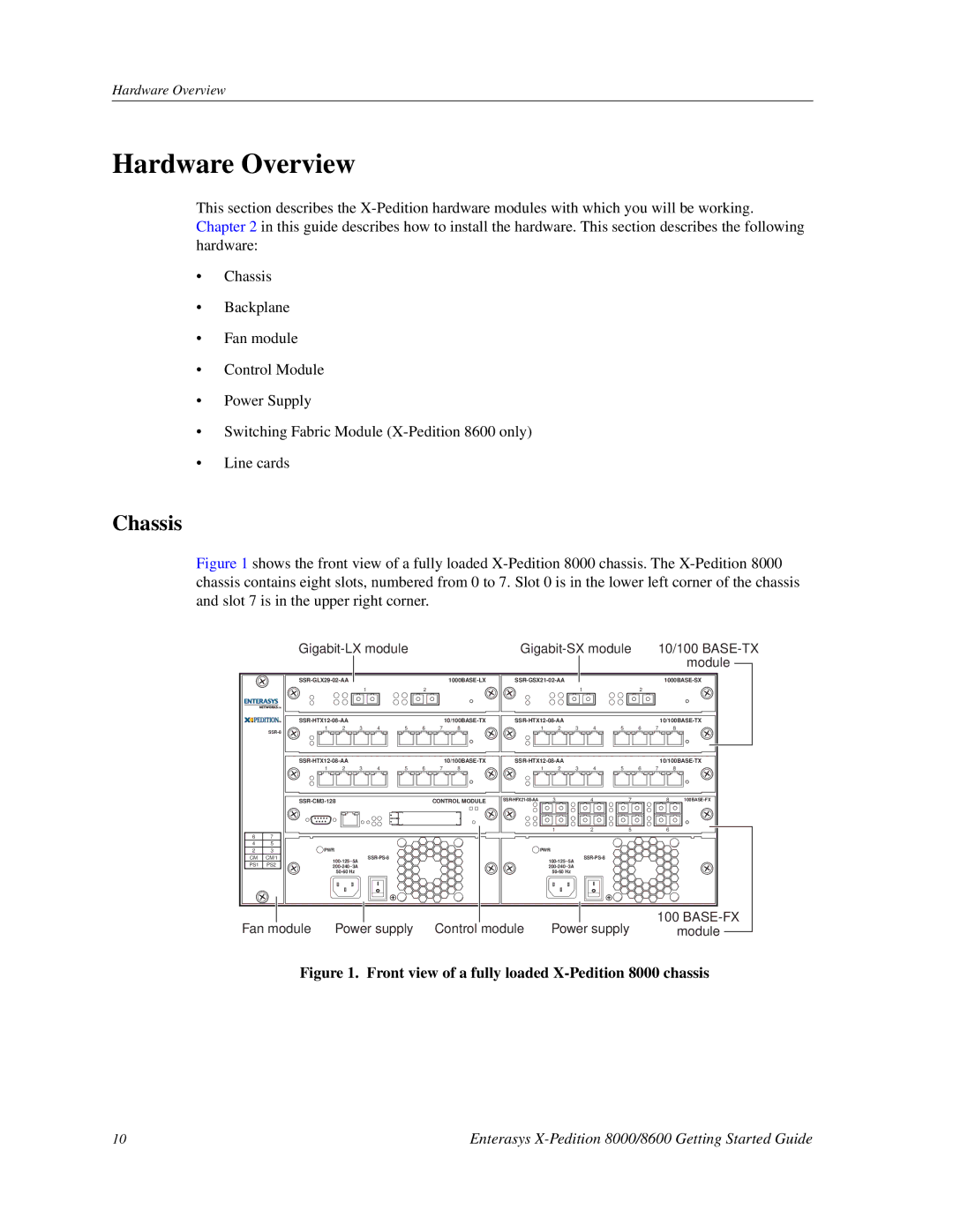
Figure 1 shows the front view of a fully loaded X-Pedition 8000 chassis. The X-Pedition 8000 chassis contains eight slots, numbered from 0 to 7. Slot 0 is in the lower left corner of the chassis and slot 7 is in the upper right corner.
|
| 10/100 | ||
|
| module |
|
|
|
|
| ||
|
|
|
|
|
|
|
|
|
|
| |||||||
|
|
|
| 1 |
|
| 2 |
|
|
|
|
| 1 |
| 2 |
|
|
|
|
|
|
|
|
|
|
|
|
| |||||||
| 1 | 2 | 3 | 4 | 5 | 6 | 7 | 8 | 1 | 2 | 3 | 4 | 5 | 6 | 7 | 8 | |
|
|
|
|
|
|
|
|
|
|
|
|
|
|
|
|
| |
|
|
|
|
|
|
|
|
|
|
| |||||||
|
| 1 | 2 | 3 | 4 | 5 | 6 | 7 | 8 | 1 | 2 | 3 | 4 | 5 | 6 | 7 | 8 |
|
|
|
|
|
| CONTROL MODULE | 3 |
| 4 |
| 7 | 8 | |||||
|
|
|
|
|
|
|
|
|
|
| 1 |
| 2 |
| 5 | 6 |
|
6 | 7 |
|
|
|
|
|
|
|
|
|
|
|
|
|
|
|
|
4 | 5 |
|
|
|
|
|
|
|
|
|
|
|
|
|
|
|
|
2 | 3 | PWR |
|
|
|
|
|
| PWR |
|
|
|
|
|
| ||
CM | CM/1 |
|
|
|
|
|
|
|
|
|
|
|
| ||||
PS1 | PS2 |
|
|
|
|
|
|
|
|
|
|
|
|
|
| ||
|
|
|
|
|
|
|
|
|
|
|
|
|
| ||||
|
|
|
|
|
|
|
|
|
|
|
|
|
| ||||
|
|
|
|
|
|
|
|
|
|
|
|
|
|
|
| ||
Fan module Power supply Control module | Power supply | 100 | |
module |
| ||
| |||
Figure 1. Front view of a fully loaded X-Pedition 8000 chassis
10 | Enterasys |