Hardware Overview
128MB DIMM), or 256MB (in two 128MB DIMMs). See Installing a Memory Upgrade on page 66 for the upgrade procedure.
External Controls
The control module has the following external controls. Where appropriate, this guide describes how to use the controls.
•Male
•
•Reset switch (RST). Use this switch to reboot the
•PCMCIA flash memory slots. These slots let you install system image software upgrades as well as older system image software versions.
Note: You can install a PCMCIA flash in slot 0 only. You cannot use two PCMCIA cards at the same time.
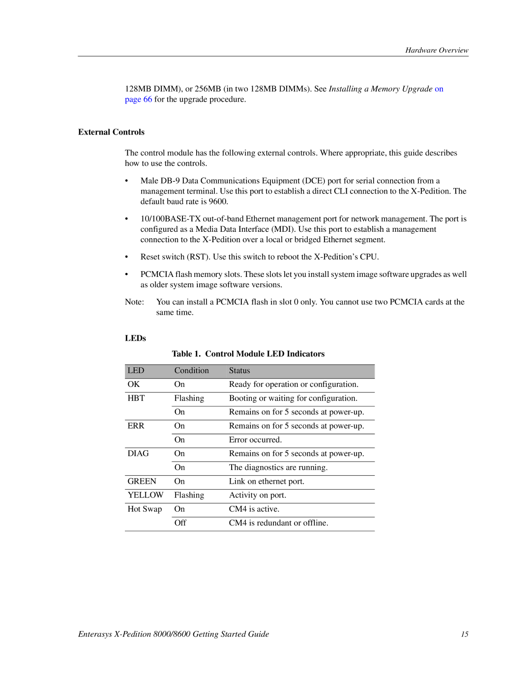
LEDs
Table 1. Control Module LED Indicators
LED | Condition | Status |
|
|
|
OK | On | Ready for operation or configuration. |
|
|
|
HBT | Flashing | Booting or waiting for configuration. |
|
|
|
| On | Remains on for 5 seconds at |
|
|
|
ERR | On | Remains on for 5 seconds at |
|
|
|
| On | Error occurred. |
|
|
|
DIAG | On | Remains on for 5 seconds at |
|
|
|
| On | The diagnostics are running. |
|
|
|
GREEN | On | Link on ethernet port. |
|
|
|
YELLOW | Flashing | Activity on port. |
|
|
|
Hot Swap | On | CM4 is active. |
|
|
|
| Off | CM4 is redundant or offline. |
|
|
|
Enterasys | 15 |