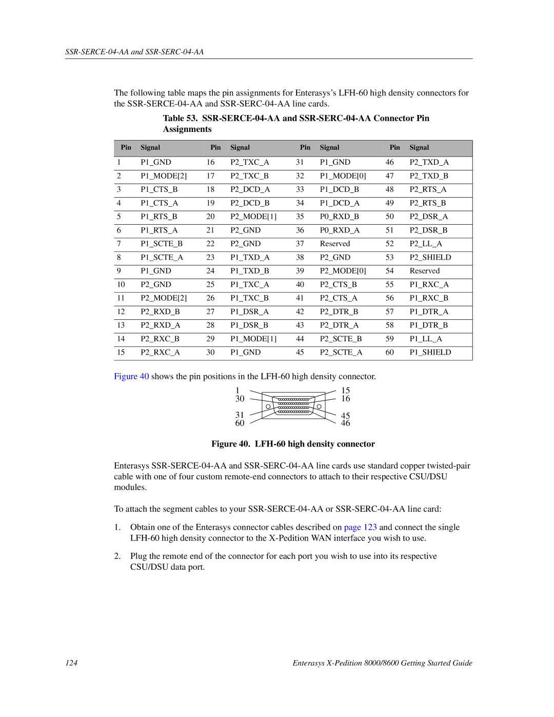
The following table maps the pin assignments for Enterasys’s
Table 53.
Assignments
Pin | Signal | Pin | Signal | Pin | Signal | Pin | Signal |
|
|
|
|
|
|
|
|
1 | P1_GND | 16 | P2_TXC_A | 31 | P1_GND | 46 | P2_TXD_A |
|
|
|
|
|
|
|
|
2 | P1_MODE[2] | 17 | P2_TXC_B | 32 | P1_MODE[0] | 47 | P2_TXD_B |
|
|
|
|
|
|
|
|
3 | P1_CTS_B | 18 | P2_DCD_A | 33 | P1_DCD_B | 48 | P2_RTS_A |
|
|
|
|
|
|
|
|
4 | P1_CTS_A | 19 | P2_DCD_B | 34 | P1_DCD_A | 49 | P2_RTS_B |
|
|
|
|
|
|
|
|
5 | P1_RTS_B | 20 | P2_MODE[1] | 35 | P0_RXD_B | 50 | P2_DSR_A |
|
|
|
|
|
|
|
|
6 | P1_RTS_A | 21 | P2_GND | 36 | P0_RXD_A | 51 | P2_DSR_B |
|
|
|
|
|
|
|
|
7 | P1_SCTE_B | 22 | P2_GND | 37 | Reserved | 52 | P2_LL_A |
|
|
|
|
|
|
|
|
8 | P1_SCTE_A | 23 | P1_TXD_A | 38 | P2_GND | 53 | P2_SHIELD |
|
|
|
|
|
|
|
|
9 | P1_GND | 24 | P1_TXD_B | 39 | P2_MODE[0] | 54 | Reserved |
|
|
|
|
|
|
|
|
10 | P2_GND | 25 | P1_TXC_A | 40 | P2_CTS_B | 55 | P1_RXC_A |
|
|
|
|
|
|
|
|
11 | P2_MODE[2] | 26 | P1_TXC_B | 41 | P2_CTS_A | 56 | P1_RXC_B |
|
|
|
|
|
|
|
|
12 | P2_RXD_B | 27 | P1_DSR_A | 42 | P2_DTR_B | 57 | P1_DTR_A |
|
|
|
|
|
|
|
|
13 | P2_RXD_A | 28 | P1_DSR_B | 43 | P2_DTR_A | 58 | P1_DTR_B |
|
|
|
|
|
|
|
|
14 | P2_RXC_B | 29 | P1_MODE[1] | 44 | P2_SCTE_B | 59 | P1_LL_A |
|
|
|
|
|
|
|
|
15 | P2_RXC_A | 30 | P1_GND | 45 | P2_SCTE_A | 60 | P1_SHIELD |
|
|
|
|
|
|
|
|
Figure 40 shows the pin positions in the LFH-60 high density connector.
1
30
31
60
15
16
45
46
Figure 40. LFH-60 high density connector
Enterasys
To attach the segment cables to your
1.Obtain one of the Enterasys connector cables described on page 123 and connect the single
2.Plug the remote end of the connector for each port you wish to use into its respective CSU/DSU data port.
124 | Enterasys |
