IP MULTICAST ROUTING
CONFIGURATION EXAMPLE
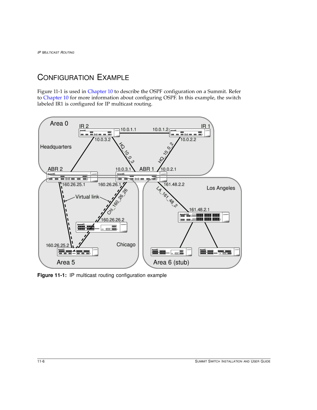
Figure 11-1 is used in Chapter 10 to describe the OSPF configuration on a Summit. Refer to Chapter 10 for more information about configuring OSPF. In this example, the switch labeled IR1 is configured for IP multicast routing.
Area 0 | IR 2 | IR 1 |
| 10.0.1.1 | 10.0.1.2 |
| 10.0.3.2 | 10.0.2.2 |
Headquarters
HQ
_
10
_ 0 _ 3
|
|
|
| 0 | _ | 2 |
|
|
| _ |
| ||
|
| 10 |
|
| ||
|
|
|
|
| ||
HQ | _ |
|
|
|
| |
|
|
|
|
| ||
|
|
|
|
|
|
ABR 2 |
| 10.0.3.1 ABR 1 10.0.2.1 | |||||||||||||||||||||||||||||||||||||
|
|
|
|
|
|
|
|
|
|
|
|
|
|
|
|
|
|
|
|
|
|
|
|
|
|
|
|
|
|
|
|
|
|
|
|
|
|
|
|
|
|
|
|
|
|
|
|
|
|
|
|
|
|
|
|
|
|
|
|
|
|
|
|
|
|
|
|
|
|
|
|
|
|
|
|
|
|
|
|
|
|
|
|
|
|
|
|
|
|
|
|
|
|
|
|
|
|
|
|
|
|
|
|
|
|
|
|
|
|
|
|
|
|
|
|
|
|
|
|
160.26.25.1160.26.26.1
Virtual link |
|
|
|
|
|
|
|
| 26 | _ | 26 | ||||
|
|
|
|
|
|
|
|
| |||||||
|
|
|
|
|
|
| _ |
|
| ||||||
|
|
|
|
|
|
|
|
|
|
| |||||
|
|
|
|
|
|
|
|
| 160 |
|
|
|
| ||
|
|
|
|
| Chi | _ |
|
|
|
|
| ||||
|
|
|
|
|
|
|
|
|
|
|
| ||||
|
|
|
|
|
|
|
|
|
|
|
|
| |||
|
|
|
| 160.26.26.2 | |||||||||||
|
|
|
|
|
|
|
|
|
|
|
|
|
|
|
|
|
|
|
|
|
|
|
|
|
|
|
|
|
|
|
|
|
|
|
|
|
|
|
|
|
|
|
|
|
|
|
|
|
|
|
|
|
|
|
|
|
|
|
|
|
|
|
|
|
|
|
|
|
|
|
|
|
|
|
|
|
|
|
|
161.48.2.2
LA _ 161 _ 48 _ 2
Los Angeles
161.48.2.1
160.26.25.2Chicago
Area 5 | Area 6 (stub) |
Figure 11-1: IP multicast routing configuration example
SUMMIT SWITCH INSTALLATION AND USER GUIDE |