Chapter 2: Setting Up Your Server
5 Insert a small screw through the disk guide and tighten the screw. Attach the remaining disk guide to the other side of the server.
Screw
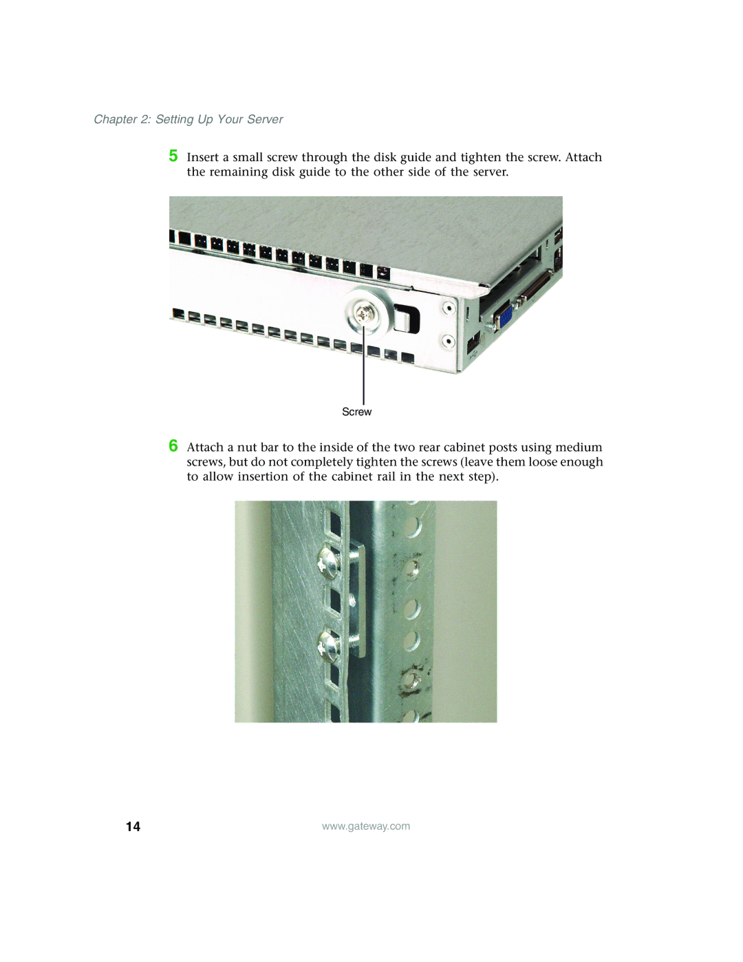
6 Attach a nut bar to the inside of the two rear cabinet posts using medium screws, but do not completely tighten the screws (leave them loose enough to allow insertion of the cabinet rail in the next step).
14 | www.gateway.com |