Chapter 4: Installing Components
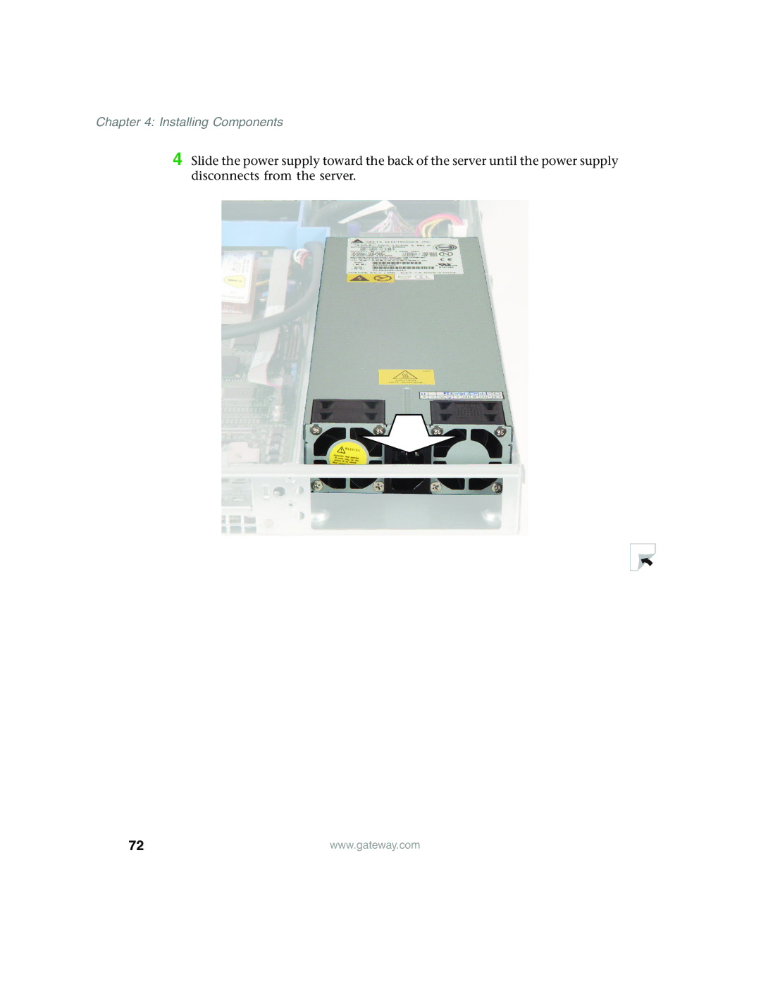
4 Slide the power supply toward the back of the server until the power supply disconnects from the server.
72 | www.gateway.com |
4 Slide the power supply toward the back of the server until the power supply disconnects from the server.
72 | www.gateway.com |