TYPE=NORMAL Normallow High Vellum
ROUGH=HIGH VELLUM=VELLUM
Print-quality menu
Print-quality menu Values Explanation
Printing menu
Printing menu Values Explanation
PCL Symbol
ERRORS=OFF
PCL Font Internal
SOURCE=INTERNAL Soft
Configuration menu
Configuration menu Values Explanation
JAM RECOVERY= Auto
Maintenance OFF
TIMEOUT=OFF Hour
Clearable JOB
Menu
O menu Values Explanation
EIO menu HP LaserJet 5100tn and 5100dtn printers
EIO menu for networked printers Values Explanation
EIO menu for networked printers Values
Explanation
Resets menu
Resets menu Explanation
To use service mode
Service mode
Service menu
Count
Value
Maintenance page count, interval, and reset
Service Mode
Service Menu
Serial number
Clear event log
Cold reset paper size
Diagnostics
Testing the printer
Resetting the printer
Cold reset
Clearing Nvram
System configuration
Printer I/O configuration
MS-DOS system configuration
Parallel MS-DOS commands
Printer maintenance
Cleaning the printer and accessories
Inside, general
Cleaning spilled toner
Using the printer cleaning
Preventive maintenance
Reset maintenance count
Expected life of components
Expected life of components Part name Part number
Functional information
Functional information Q1860-90918
Printer subsystems
Paper-feed subsystem
Power supply system
Ac/dc power distribution
Overcurrent overvoltage protection
High-voltage power distribution
High-voltage power supply circuit
Toner-cartridge detection
Dc controller system
Dc controller PCA
Q1860-90918 Functional information
Solenoids, sensors, clutches, and switches
Laser and scanner drive
Paper-motion monitoring and control
Engine test
Motors
Main-motor control
Formatter system
PowerSave
Resolution Enhancement technology
EconoMode
Input/output
Read-only memory and random-access memory RAM
Nonvolatile random-access memory
Printer memory
Memory Enhancement technology
Protect
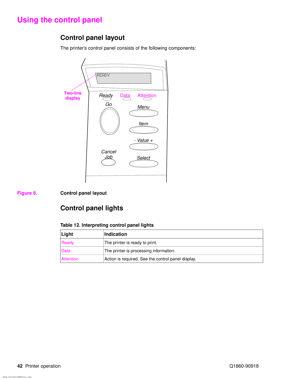
Control panel
Image-formation system
Image-formation system
Toner cartridge
Photosensitive drum
Cleaning the drum
Cleaning the drum
Conditioning the drum
Primary charging roller
Writing the image
Writing the image
Developing the image
Developing the image
Transferring the image
Transferring the image
Image fusing/variable fusing temperature
Variable fusing temperature
Fusing temperature control
Paper feed system
Paper path
Clutches and sensors
Printing from Tray
Tray 2 Paper path
Paper skew correction
Printing from the optional 500-sheet and 250-sheet Trays
Sheet paper feeder
500-sheet paper feeder
Paper jam
Duplexer
Reversing/refeed system
Paper-feed belt assembly removal 2
Tray 1 shaft
Tray 1 shaft removal 1 of 2, right side view of printer
Tray 1 shaft removal 2
Tray 2 shaft
Tray 2 shaft removal left side view of printer
Reinstallation of Tray 2 shaft
Tray 1 lift plate
Tray 1 lift plate removal
Paper guide
Paper guide removal
Top-of-page sensor
Top-of-page sensor removal bottom of printer
Face-down bin-full sensor lever
Face-down bin-full sensor lever removal
Accessory interface connector
Accessory interface connector removal left side of printer
Registration assembly
Registration assembly removal 1
Registration assembly removal 2
Upper delivery assembly
Upper delivery assembly removal
Delivery roller
Delivery roller removal 1
Delivery roller removal 2
Laser/scanner assembly
Laser/scanner assembly removal top, inside view of printer
Main motor
Main motor removal rear view
Toner cartridge guides
Toner cartridge guide removal shown from right side
Power inlet assembly
Power inlet assembly removal
Optional 250-sheet feeder
Separation pad
Pickup roller
Sensing flag
Optional 250-sheet feeder sensing flag removal 1
Control PCA
Optional 250-sheet feeder control PCA removal 1
Optional 250-sheet feeder control PCA removal 3
Paper-size spring assembly
Optional 500-sheet feeder
Covers and base frame
Sheet feeder removal 2 of 2, top view with covers removed
Tray indicator assembly
Tray indicator assembly removal
Left front corner cover installation
Installing the left front corner cover
Sheet feeder feed roller
Sheet feeder feed roller removal
Sheet feeder pickup roller
Sheet feeder pickup roller removal 1
Sheet feeder PCAs
Sheet feeder power connector
Power connector removal
Sheet feeder separation roller
Separation roller removal
Troubleshooting
Troubleshooting process
Major steps for troubleshooting
Troubleshooting process flow
See Printer Messages on 193 to Understand Correct Problem
See Image quality on 207 Compare pages To samples
Troubleshooting the printing system
Preliminary operating checks
Power on
Power on defect or blank display Problem Action
No ac power Cause Action
No dc power Cause Action
Printing an engine test
Display
Engine test button location
Event log
Interpret the event log
View the event log at the control panel
Print the event log
Printer messages
Printer messages Message Explanation or recommended action
Do not Power OFF
Do not Power OFF Flash Device
Install Toner
Initializing
Memory Settings
Maintenance
Resend Upgrade
Changed
Printer Error
Unable to
Store JOB
USE Type
Buffer Overflow
Parallel I/O
Transmission
Unexpected
Fuser Error