Hp LaserJet Service5100tn 5100dtn 5100Le
Page
Service
Copyright Hewlett -Packard Company
Contents
Printer operation
Q1860-90918
Functional information
Removing and replacing parts
Troubleshooting
Q1860-90918
Figures
Tray 1 inner cover removal 2 of 2, front of printer
Sheet feeder feed roller removal 178
275
Tables
251
Printer description
Overview
Printer features
Printer features
HP LaserJet 5100tn printer
Printer information
HP LaserJet 5100 printer
HP LaserJet 5100dtn printer
Q1860A Q1861A Q1862A Q1863A
Identification
Model and serial numbers
Environmental and power requirements
Site requirements
Space requirements
139.8 cm 55 62.5 cm 24.6
Printer weight without toner cartridge
Environmental specifications Operating Storage
Environmental requirements
Paper specifications
Paper specifications, duplexer Dimensions Weight
Supported types of paper
Guidelines for using paper
Media issues Symptom Problem with paper Solution
Paper weight equivalence table
Vellum
Labels
Transparencies
Envelopes
Envelope margins
Envelopes that have double side seams
Envelopes that have adhesive strips or flaps
Envelope storage
Card stock and heavy paper
Card stock construction
Card stock guidelines
Canadian DOC regulations
Safety information
Laser safety statement
FCC regulations
Material Safety Data Sheet
Laser statement for Finland Luokan 1 laserlaite
This HP LaserJet printer design reduces
Environmental product stewardship
Protecting the environment
Printer design eliminates
Service approach
Limited warranty for the print cartridge
Service approach
Warranty
Regulatory information
Service and support
Worldwide service and support offices
Europe
Asia-Pacific countries/regions
Service approach Q1860-90918
Printer operation
Control panel lights
Using the control panel
Control panel layout
Interpreting control panel lights
Control panel keys
Control panel keys Key Function
Settings and defaults
Settings and defaults
Setting the display language
Setting or default Explanation
To change a control panel setting
Control panel menus
To print a control panel menu map
Jobname
Private/stored jobs menu
Private/stored jobs menu
COPIES=X
Information menu
Information menu Explanation
Paper-handling menu Item/default Values Explanation
Paper-handling menu
TYPE=NORMAL Normallow High Vellum
ROUGH=HIGH VELLUM=VELLUM
Print-quality menu
Print-quality menu Values Explanation
Printing menu
Printing menu Values Explanation
PCL Font Internal
PCL Symbol
ERRORS=OFF
SOURCE=INTERNAL Soft
Configuration menu
Configuration menu Values Explanation
TIMEOUT=OFF Hour
JAM RECOVERY= Auto
Maintenance OFF
Clearable JOB
Menu
O menu Values Explanation
EIO menu HP LaserJet 5100tn and 5100dtn printers
EIO menu for networked printers Values Explanation
EIO menu for networked printers Values
Explanation
Resets menu
Resets menu Explanation
Service mode
Service menu
To use service mode
Count
Value
Service Menu
Maintenance page count, interval, and reset
Service Mode
Serial number
Cold reset paper size
Diagnostics
Clear event log
Cold reset
Testing the printer
Resetting the printer
Clearing Nvram
MS-DOS system configuration
System configuration
Printer I/O configuration
Parallel MS-DOS commands
Printer maintenance
Cleaning the printer and accessories
Inside, general
Cleaning spilled toner
Using the printer cleaning
Expected life of components
Preventive maintenance
Reset maintenance count
Expected life of components Part name Part number
Functional information
Functional information Q1860-90918
Printer subsystems
Paper-feed subsystem
Power supply system
Ac/dc power distribution
Overcurrent overvoltage protection
High-voltage power distribution
High-voltage power supply circuit
Dc controller PCA
Toner-cartridge detection
Dc controller system
Q1860-90918 Functional information
Paper-motion monitoring and control
Solenoids, sensors, clutches, and switches
Laser and scanner drive
Engine test
Motors
Main-motor control
PowerSave
Resolution Enhancement technology
Formatter system
EconoMode
Input/output
Printer memory
Read-only memory and random-access memory RAM
Nonvolatile random-access memory
Memory Enhancement technology
Protect
Control panel
Image-formation system
Image-formation system
Toner cartridge
Cleaning the drum
Cleaning the drum
Photosensitive drum
Conditioning the drum
Primary charging roller
Writing the image
Writing the image
Developing the image
Developing the image
Transferring the image
Transferring the image
Image fusing/variable fusing temperature
Variable fusing temperature
Fusing temperature control
Paper feed system
Paper path
Clutches and sensors
Printing from Tray
Tray 2 Paper path
Paper skew correction
Printing from the optional 500-sheet and 250-sheet Trays
Sheet paper feeder
500-sheet paper feeder
Paper jam
Duplexer
Reversing/refeed system
Reversing system
Duplexer
Paper jam in the duplexer
Basic sequence of operation
Basic sequence of operation Period Timing Purpose Remark
Functional information Q1860-90918
Q1860-90918 Functional information
Functional information Q1860-90918
Removing and replacing parts
Removing and replacing parts Q1860-90918
User-installable accessories
Memory upgrade
If an optional duplexer is installed
Checking memory installation
Installing EIO cards or mass-storage devices
Paper-handling accessories
Removing loose toner
Before you begin
Replacing printer parts
Required tools
Parts removal order
Covers
Rear door and rear output bin
Rear door and rear output bin removal 2
Fuser
Fuser removal rear view of printer
Top cover
Top cover removal 1
Top cover removal 2
Control panel overlay and control panel
Control panel overlay removal
Control panel removal
Toner cartridge door assembly
Front cover and Tray
Front cover removal
Front cover pins
Front cover pins removal
Face-down cover
Face-down cover removal 1
Left and right side covers
Side covers removal
Tray 1 inner cover
Tray 1 inner cover removal 1 of 2, inner cover flag
Tray 1 inner cover removal 2 of 2, front of printer
Right and left corner covers
Corner covers removal
Internal assemblies
Internal assemblies Explanation
Transfer-roller assembly
Transfer-roller assembly removal 1
Transfer-roller assembly removal 2
To reinstall
Reinstalling the transfer roller
Paper-handling PCA
Paper-handling PCA removal
Top margin adjustment
Adjusting the top margin
Location of VR401 on the paper-handling PCA
Main gear assembly
Main gear assembly removal 1 of 2, left side
Main gear assembly removal 2
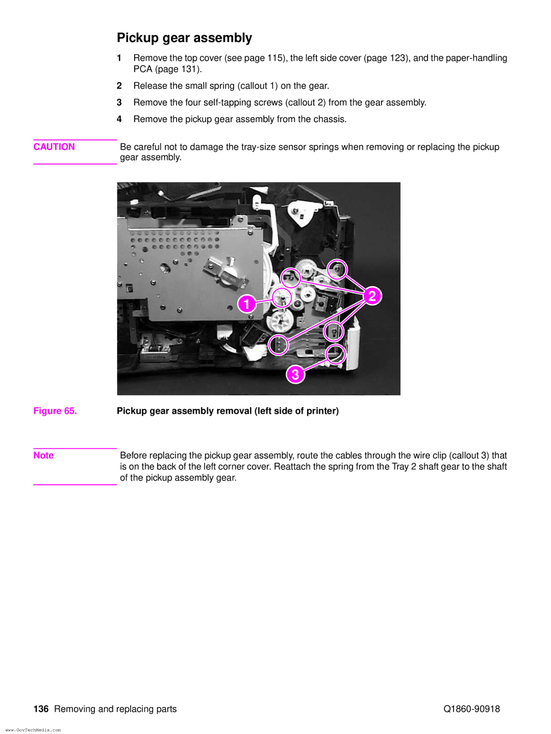
Pickup gear assembly
Pickup gear assembly removal left side of printer
Tray 1 pickup solenoid
Tray 1 pickup solenoid removal
Fan
Fan removal right side of printer
Formatter assembly
Formatter assembly removal
Tray 1 roller
Tray 1 roller removal
Tray 1 separation pad
Tray 1 separation pad removal 2
Tray 2 pickup roller
Tray 2 pickup roller removal bottom of the printer
Tray 2 separation pad
Tray 2 separation pad removal 1
Paper-feed roller assembly
Page
Dc controller and power supply
Dc controller assembly removal 1 of 3, rear view of printer
Dc controller assembly removal 2 of 3, long screws
Paper-feed belt assembly
Paper-feed belt assembly removal 1
Paper-feed belt assembly removal 2
Tray 1 shaft
Tray 1 shaft removal 1 of 2, right side view of printer
Tray 1 shaft removal 2
Tray 2 shaft
Tray 2 shaft removal left side view of printer
Reinstallation of Tray 2 shaft
Tray 1 lift plate
Tray 1 lift plate removal
Paper guide
Paper guide removal
Top-of-page sensor
Top-of-page sensor removal bottom of printer
Face-down bin-full sensor lever
Face-down bin-full sensor lever removal
Accessory interface connector
Accessory interface connector removal left side of printer
Registration assembly
Registration assembly removal 1
Registration assembly removal 2
Upper delivery assembly
Upper delivery assembly removal
Delivery roller
Delivery roller removal 1
Delivery roller removal 2
Laser/scanner assembly
Laser/scanner assembly removal top, inside view of printer
Main motor
Main motor removal rear view
Toner cartridge guides
Toner cartridge guide removal shown from right side
Power inlet assembly
Power inlet assembly removal
Optional 250-sheet feeder
Separation pad
Pickup roller
Sensing flag
Optional 250-sheet feeder sensing flag removal 1
Control PCA
Optional 250-sheet feeder control PCA removal 1
Optional 250-sheet feeder control PCA removal 3
Paper-size spring assembly
Optional 500-sheet feeder
Covers and base frame
Sheet feeder removal 2 of 2, top view with covers removed
Tray indicator assembly
Tray indicator assembly removal
Left front corner cover installation
Installing the left front corner cover
Sheet feeder feed roller
Sheet feeder feed roller removal
Sheet feeder pickup roller
Sheet feeder pickup roller removal 1
Sheet feeder PCAs
Sheet feeder power connector
Power connector removal
Sheet feeder separation roller
Separation roller removal
Troubleshooting
Troubleshooting process
Major steps for troubleshooting
Troubleshooting process flow
See Printer Messages on 193 to Understand Correct Problem
See Image quality on 207 Compare pages To samples
Troubleshooting the printing system
Preliminary operating checks
Power on
Power on defect or blank display Problem Action
No ac power Cause Action
No dc power Cause Action
Display
Engine test button location
Printing an engine test
Event log
View the event log at the control panel
Print the event log
Interpret the event log
Printer messages
Printer messages Message Explanation or recommended action
Install Toner
Do not Power OFF
Do not Power OFF Flash Device
Initializing
Resend Upgrade
Memory Settings
Maintenance
Changed
Store JOB
Printer Error
Unable to
USE Type
Transmission
Buffer Overflow
Parallel I/O
Unexpected
Fuser Error
Printer Error
Cycle Power to
Cycle Power
Device Failure
Check Cables
8x.yyyy
General paper-path troubleshooting
ProblemAction
Paper-path test
Press Item until Print Paper Path Test appears
Information pages
Menu map
Configuration
Configuration page see for category explanations
Verify the installed options
Configuration page categories
Image quality
Check the toner cartridge
Image quality checks Action
EconoMode
Image defects
Black lines in paper path direction Possible cause Action
Correctly Defective toner cartridge
Black
Possible cause Action
Blank
Cartridge
HP LaserJet Printer Family Paper Specification Guide
Character voids and dropouts
Creases Possible cause Action
Curl Possible cause Action
Dark print Possible causeAction
Dirt on back Possible cause Action
Distorted image Possible cause Action
Dots in the paper-path direction
Faded or light print Possible cause Action
Gray background Possible cause Action
Improperly
Loose toner or toner smear
Repetitive defects
Skew Possible cause Action
Smudged lines either direction Possible cause Action
Toner specks see also Dots on Possible cause Action
White lines in the paper-path direction
Damage to the print drum
Repetitive defect ruler
Repetitive defect ruler
Image system troubleshooting
Half self-test functional check
Drum rotation functional check
Jetdirect configuration
Interface troubleshooting
EIO troubleshooting
Communications check
Jetdirect configuration
Reference diagrams
Locations of components
Paper path clutches, solenoids, and motors
Sheet paper feeder
Sheet paper feeder
Sheet paper feeder
Sheet paper feeder
Duplexer
Troubleshooting Q1860-90918
Q1860-90918 Troubleshooting
Sensors and signals
Paper path and components see , , and for accessories
Sensors, switches, clutches, and solenoids Name
Printer sensors
Duplexer sensors
Printer switches
Sheet feeder switches
Motors, fans, and fuser heaters see on
FM1
Connectors main unit
Connectors duplexer and 250-sheet paper feeder
Connectors 500-sheet paper feeder
PCAs
PCA duplexer PCAs Name Function
PCA
Clutches and solenoids
Clutches and solenoids duplexer Symbol Name of symbol Code
OFF A4R
Dc controller inputs and outputs
Dc controller I/O 1
Dc controller I/O 2
Dc controller I/O 3
Dc controller I/O 4
Troubleshooting Q1860-90918
Parts and diagrams
Parts and diagrams Q1860-90918
Support
Ordering parts and supplies, and getting support
Related documentation and software
Ordering parts
Accessories and supplies
Common hardware and replacement cables
Screws used in the printer Description Part number
Replaceable cables Description Part Number
Diagrams and parts lists
Assembly locations 1
Registration roller assembly Fuser Tray Tray 2 pickup roller
Parts and diagrams Q1860-90918
Q1860-90918 Parts and diagrams
Internal components 1
Q1860-90918 Parts and diagrams
Internal components 2
Q1860-90918 Parts and diagrams
See
See
Parts and diagrams Q1860-90918
Q1860-90918 Parts and diagrams
Parts and diagrams Q1860-90918
Paper feed roller assembly
Item number Part number Quantity Description
RG5-4916-000CN Registration roller assembly
Q1860-90918 Parts and diagrams
Parts and diagrams Q1860-90918
Q1860-90918 Parts and diagrams
Parts and diagrams Q1860-90918
See figure
Fuser Item number Part number Quantity Description
Sheet feeder Item number Part number Quantity Description
Parts and diagrams Q1860-90918
Sheet feeder 1 Item number Part number Quantity Description
Sheet feeder 2
Sheet feeder 2 Item number Part number Quantity Description
Parts and diagrams Q1860-90918
Duplexer Item number Part number Quantity Description
Alphabetical parts list
Alphabetical parts list Description Part number
Alphabetical parts list Description Part number
Cable, ribbon, paper-handling PCA to dc controller
Alphabetical parts list Description Part number
Numerical parts list
Numerical parts list Part number Description
Numerical parts list Part number Description
Cable, ribbon, paper-handling PCA to dc controller
Numerical parts list Part number Description
Parts and diagrams Q1860-90918
Index
Index
See also removing
EIO
IPX/SPX
MS-DOS
Q1860-90918
Index
Q1860-90918 Index
TCP/IP
See also testing
Index Q1860-90918
Page
Copyright 2002 Hewlett-Packard Company