HP Z220 CMT Workstation system board component
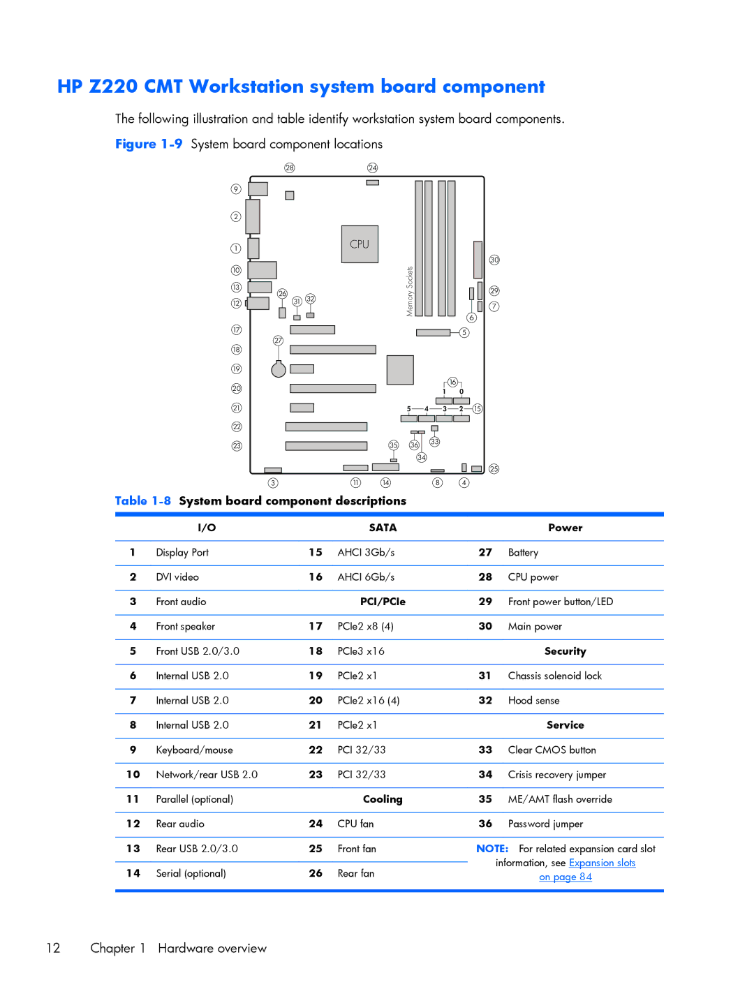
The following illustration and table identify workstation system board components. Figure
9
2
1
10
28
24
CPU
30 |
Sockets |
13
12
17
18
19
20
21
22
26
27
31 32
Memory | 29 | |
7 | ||
6 | ||
| ||
| 5 |
16
1 0
5 4 3 2 15
23
3
35 | 36 | 33 |
| ||
| 34 |
|
25 |
11 | 14 | 8 | 4 |
Table 1-8 System board component descriptions
| I/O |
| SATA |
| Power |
|
|
|
|
|
|
1 | Display Port | 15 | AHCI 3Gb/s | 27 | Battery |
|
|
|
|
|
|
2 | DVI video | 16 | AHCI 6Gb/s | 28 | CPU power |
|
|
|
|
|
|
3 | Front audio |
| PCI/PCIe | 29 | Front power button/LED |
|
|
|
|
|
|
4 | Front speaker | 17 | PCIe2 x8 (4) | 30 | Main power |
|
|
|
|
|
|
5 | Front USB 2.0/3.0 | 18 | PCIe3 x16 |
| Security |
|
|
|
|
|
|
6 | Internal USB 2.0 | 19 | PCIe2 x1 | 31 | Chassis solenoid lock |
|
|
|
|
|
|
7 | Internal USB 2.0 | 20 | PCIe2 x16 (4) | 32 | Hood sense |
|
|
|
|
|
|
8 | Internal USB 2.0 | 21 | PCIe2 x1 |
| Service |
|
|
|
|
|
|
9 | Keyboard/mouse | 22 | PCI 32/33 | 33 | Clear CMOS button |
|
|
|
|
|
|
10 | Network/rear USB 2.0 | 23 | PCI 32/33 | 34 | Crisis recovery jumper |
|
|
|
|
|
|
11 | Parallel (optional) |
| Cooling | 35 | ME/AMT flash override |
|
|
|
|
|
|
12 | Rear audio | 24 | CPU fan | 36 | Password jumper |
|
|
|
|
| |
13 | Rear USB 2.0/3.0 | 25 | Front fan | NOTE: For related expansion card slot | |
|
|
|
|
| information, see Expansion slots |
14 | Serial (optional) | 26 | Rear fan |
| |
| on page 84 | ||||
|
|
|
|
|
|
12 Chapter 1 Hardware overview