HP Z220 CMT Workstation system board architecture
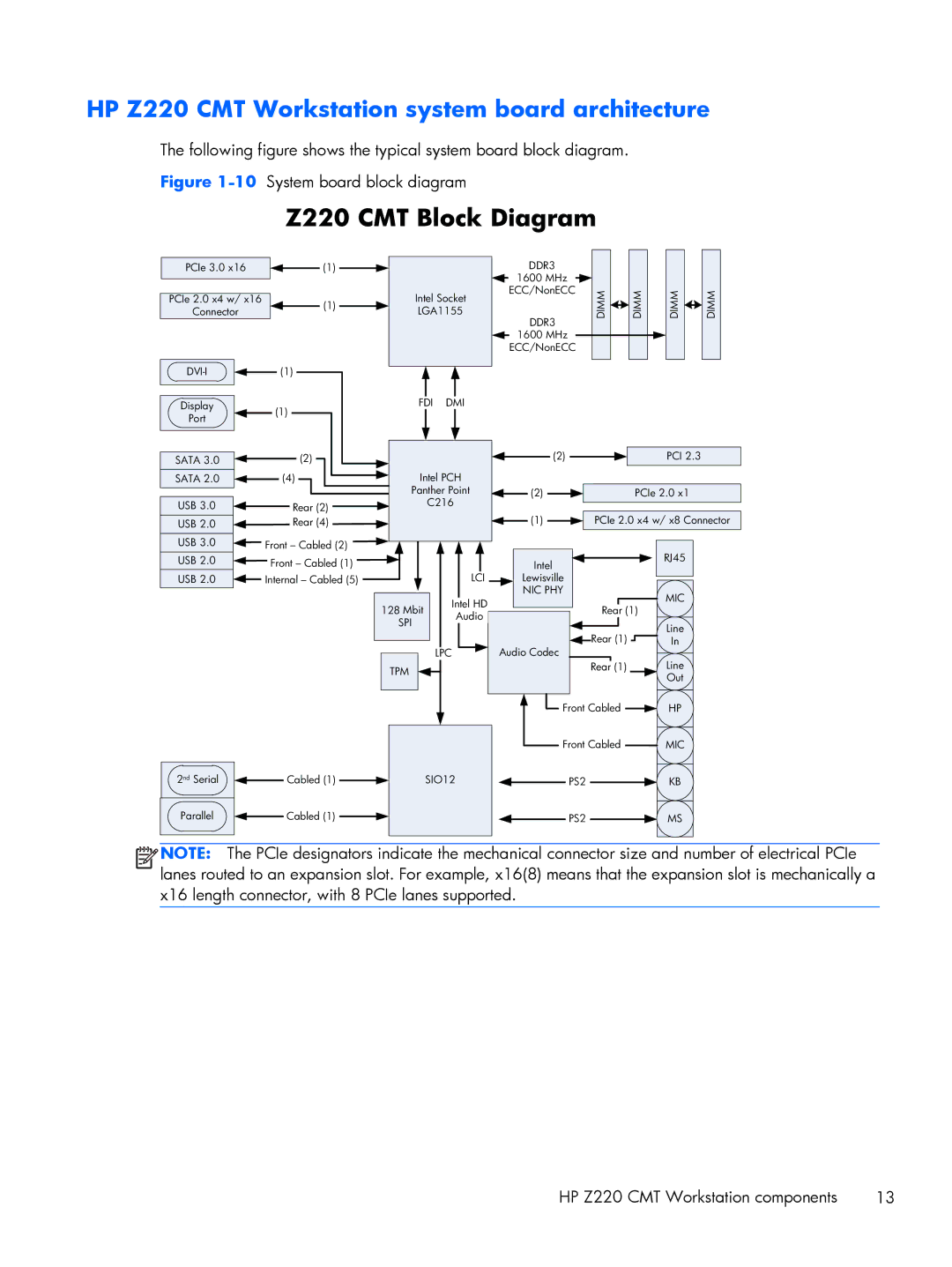
The following figure shows the typical system board block diagram. Figure
Z220 CMT Block Diagram
PCIe 3.0 x16
PCIe 2.0 x4 w/ x16
Connector
(1)x
(1)x
(1)x
Intel Socket
LGA1155
DDR3
1600 MHz
ECC/NonECC
DDR3
1600 MHz
ECC/NonECC
DIMM |
|
|
| DIMM |
|
|
| ||
|
|
|
|
|
DIMM |
|
|
| DIMM |
|
| |||
|
|
|
|
|
Display | (1)x | FDI | DMI |
|
|
|
Port |
|
|
|
|
| |
|
|
|
|
|
| |
SATA 3.0 | (2)x |
|
| (2)x |
| PCI 2.3 |
SATA 2.0 | (4)x | Intel PCH |
|
|
| |
|
| Panther Point | (2)x |
| PCIe 2.0 x1 | |
USB 3.0 | Rear (2)x | C216 | (1)x | PCIe 2.0 x4 w/ x8 Connector | ||
USB 2.0 | Rear (4)x |
|
| |||
USB 3.0 | Front – Cabled (2)x |
|
|
|
| RJ45 |
USB 2.0 | Front – Cabled (1)x |
|
| Intel |
| |
| LCIx |
|
| |||
USB 2.0 | Internal – Cabled (5)x |
| Lewisville |
|
| |
|
|
|
| NIC PHY |
| MIC |
|
| Mbit | Intel HD |
|
| |
| 128 |
| Rear (1) | |||
| Audio |
| ||||
| SPI |
|
| Line | ||
|
|
|
| |||
|
|
|
|
| Rear (1)x | |
|
|
| LPC | Audio Codec | In | |
|
|
|
| Line | ||
| TPM |
|
| Rear (1)x | ||
|
|
|
| Out | ||
|
|
|
|
|
| |
|
|
|
| Front Cabledx | HP | |
|
|
|
| Front Cabledx | MIC | |
2nd Serial | Cabled (1)x | SIO12 | PS2x |
| KB | |
Parallel | Cabled (1)x |
|
| PS2x |
| MS |
![]()
![]()
![]()
![]() NOTE: The PCIe designators indicate the mechanical connector size and number of electrical PCIe lanes routed to an expansion slot. For example, x16(8) means that the expansion slot is mechanically a x16 length connector, with 8 PCIe lanes supported.
NOTE: The PCIe designators indicate the mechanical connector size and number of electrical PCIe lanes routed to an expansion slot. For example, x16(8) means that the expansion slot is mechanically a x16 length connector, with 8 PCIe lanes supported.
HP Z220 CMT Workstation components | 13 |
