Chassis Features and Controls
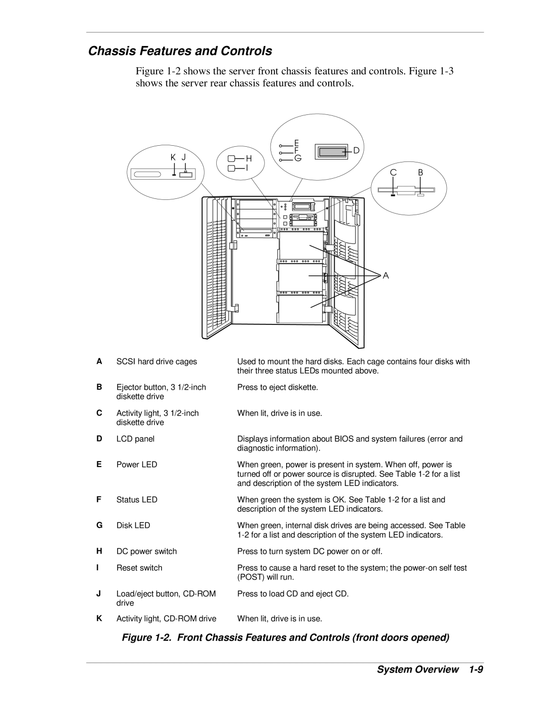
Figure 1-2 shows the server front chassis features and controls. Figure 1-3 shows the server rear chassis features and controls.
|
| E | D |
K J | H | F | |
G |
| ||
| I |
| C B |
|
|
|
A
ASCSI hard drive cages
BEjector button, 3
CActivity light, 3
DLCD panel
EPower LED
Used to mount the hard disks. Each cage contains four disks with their three status LEDs mounted above.
Press to eject diskette.
When lit, drive is in use.
Displays information about BIOS and system failures (error and diagnostic information).
When green, power is present in system. When off, power is turned off or power source is disrupted. See Table
F | Status LED | When green the system is OK. See Table |
|
| description of the system LED indicators. |
G | Disk LED | When green, internal disk drives are being accessed. See Table |
|
| |
H | DC power switch | Press to turn system DC power on or off. |
I | Reset switch | Press to cause a hard reset to the system; the |
|
| (POST) will run. |
J | Load/eject button, | Press to load CD and eject CD. |
| drive |
|
K | Activity light, | When lit, drive is in use. |