O N M L
G | A |
H | B |
I | C |
J | D |
F | E |
P
K
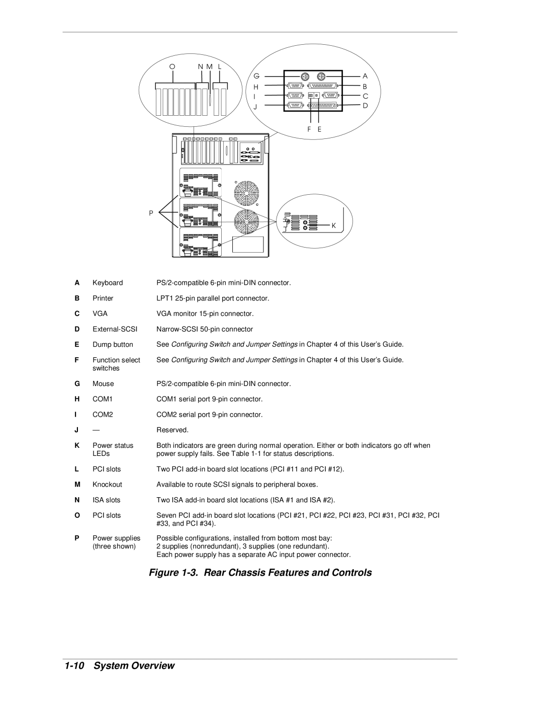
A | Keyboard | |
B | Printer | LPT1 |
C | VGA | VGA monitor |
D | ||
E | Dump button | See Configuring Switch and Jumper Settings in Chapter 4 of this User’s Guide. |
F | Function select | See Configuring Switch and Jumper Settings in Chapter 4 of this User’s Guide. |
| switches |
|
G | Mouse | |
H | COM1 | COM1 serial port |
I | COM2 | COM2 serial port |
J | — | Reserved. |
K | Power status | Both indicators are green during normal operation. Either or both indicators go off when |
| LEDs | power supply fails. See Table |
L | PCI slots | Two PCI |
M | Knockout | Available to route SCSI signals to peripheral boxes. |
N | ISA slots | Two ISA |
O | PCI slots | Seven PCI |
|
| #33, and PCI #34). |
P | Power supplies | Possible configurations, installed from bottom most bay: |
| (three shown) | 2 supplies (nonredundant), 3 supplies (one redundant). |
|
| Each power supply has a separate AC input power connector. |
|
| Figure |