I | H |
J |
|
T | G |
| |
K | F |
| |
L |
|
M |
|
| E |
| D |
N | C |
| |
O |
|
P | B |
| |
Q |
|
R | A |
M |
|
S | M |
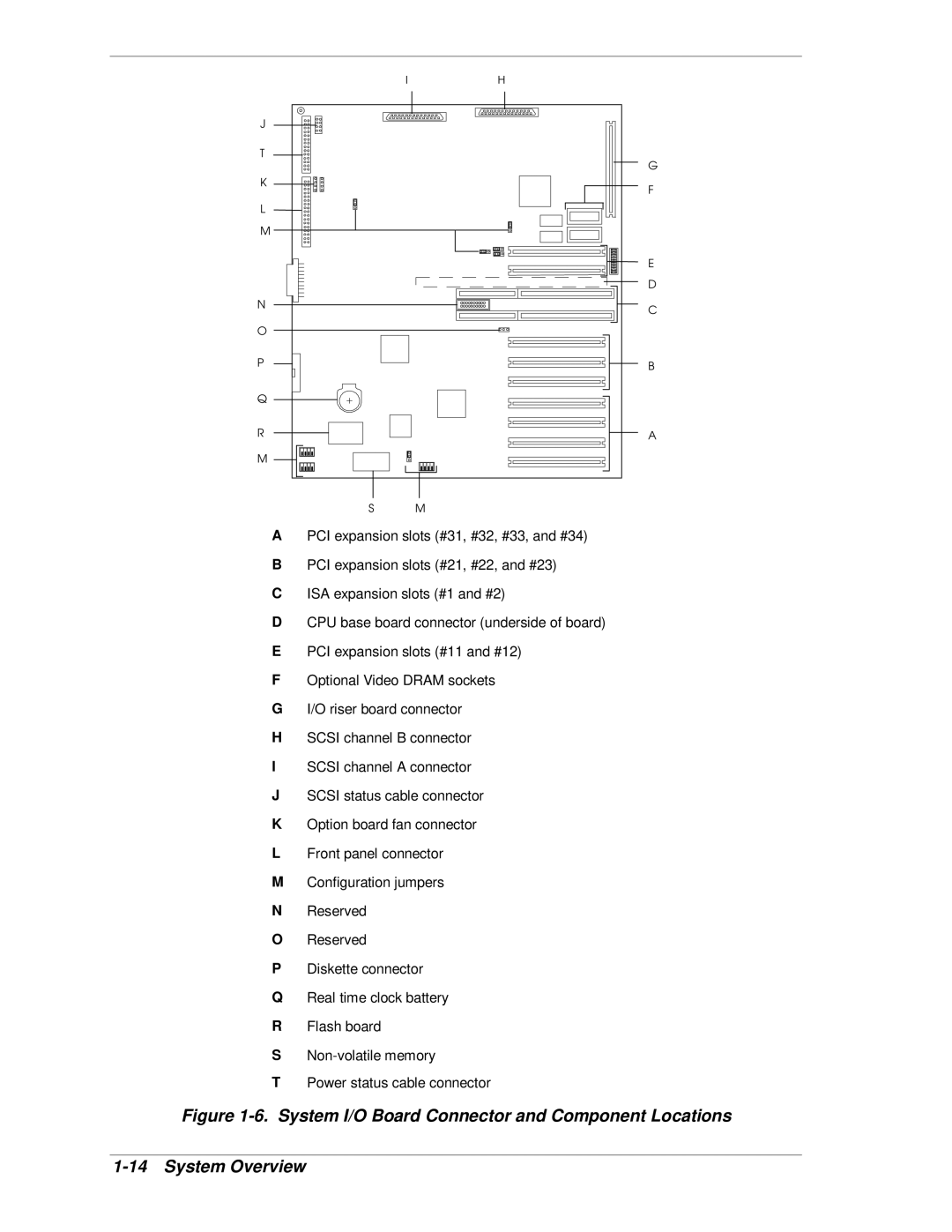
APCI expansion slots (#31, #32, #33, and #34)
BPCI expansion slots (#21, #22, and #23)
CISA expansion slots (#1 and #2)
DCPU base board connector (underside of board)
EPCI expansion slots (#11 and #12)
FOptional Video DRAM sockets
GI/O riser board connector
HSCSI channel B connector
ISCSI channel A connector
JSCSI status cable connector
KOption board fan connector
LFront panel connector
MConfiguration jumpers
NReserved
OReserved
PDiskette connector
QReal time clock battery
RFlash board
S
TPower status cable connector