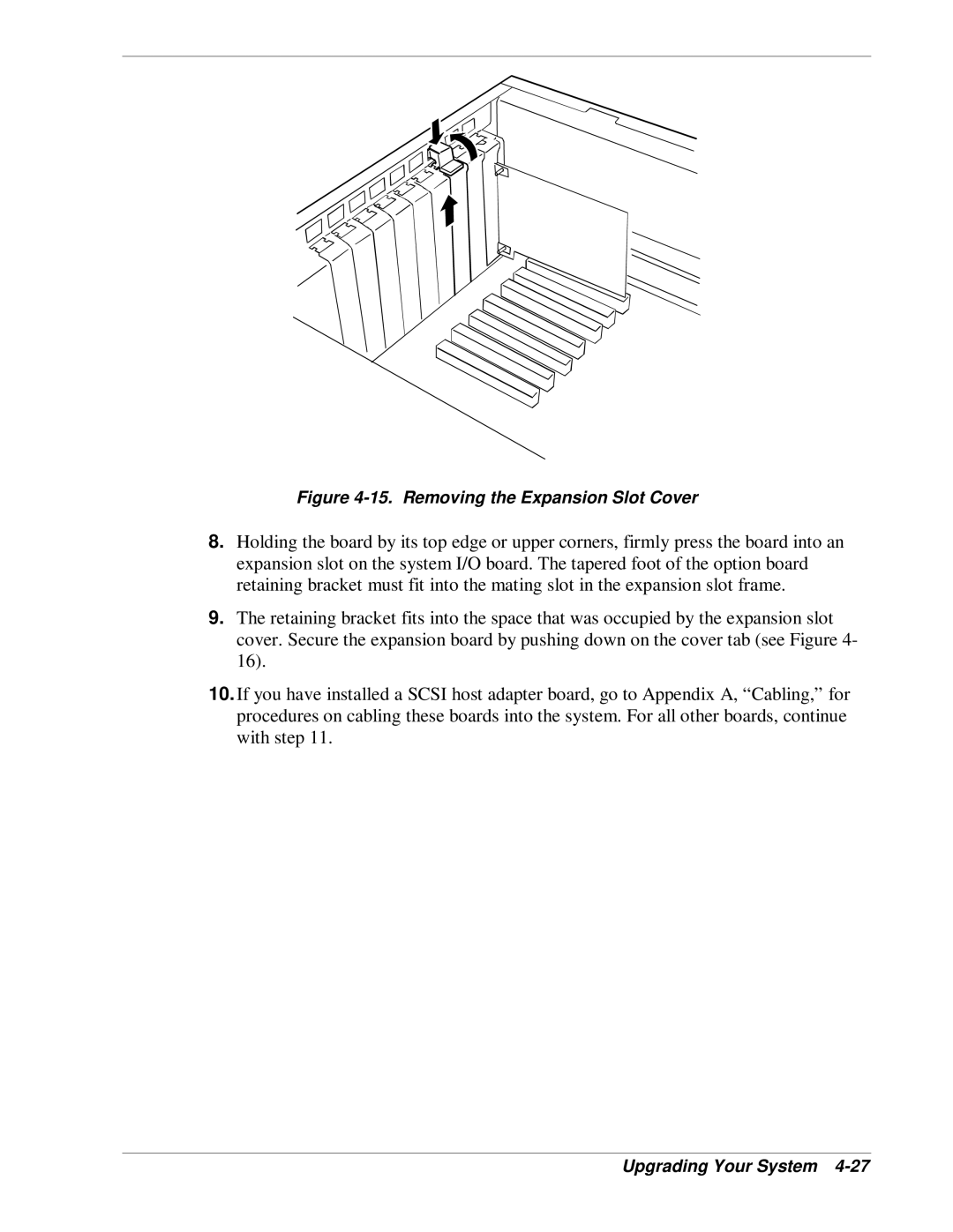
Figure 4-15. Removing the Expansion Slot Cover
8.Holding the board by its top edge or upper corners, firmly press the board into an expansion slot on the system I/O board. The tapered foot of the option board retaining bracket must fit into the mating slot in the expansion slot frame.
9.The retaining bracket fits into the space that was occupied by the expansion slot cover. Secure the expansion board by pushing down on the cover tab (see Figure 4- 16).
10.If you have installed a SCSI host adapter board, go to Appendix A, “Cabling,” for procedures on cabling these boards into the system. For all other boards, continue with step 11.