ΜPD75402A
Page
Major Revisions in This Version
Remarks
Content to be read carefully
Instruction Functions and Application
Latest documents should be used for design purposes, etc
Related Documentation Device Related Documents
Development Tool Related Documents
Other Related Documents
Contents
Clock Generation Circuit
Basic Interval Timer
Interrupt Control Circuit Configuration
Digital INPUT/OUTPUT Ports
Standby Mode Application
Standby Mode Setting and Operation States
Standby Mode Reset
Operation After Standby Mode Reset
Contents of Figures
Fig. No Title
Table No Title
Contents of Tables
ECR VCR
General
FAX PPC
For details, see Interrupt Functions
General Outline of Functions
Quality Grade
General Ordering Information and Quality Grade
Ordering Information
VPP
PORT6
Block Diagram
PORT0 PORT1 PORT2 PORT3 PORT5
INT0 Interrupt INT2 Control
VPP NC
General PIN Configuration
SCK
SO/SB0
Prom mode
NC V SS NC P22/PCL
2 44-Pin Plastic QFP 10mm Normal operating mode
NC NC NC P50
P01/SCK
A2 NC NC NC NC
PIN Functions
INT0
ΜPD75402A PIN Function List Port Pin List
SCK
SO/SB0
SCK SB0
Port 0’s, 1’s Dual-Function Pins
PIN Functions Normal Operating Mode
PCL ..... Port 2 Dual-Function Output
4 INT0 ..... Port 1 Dual-Function Input
5 INT2 ..... Port 1 Dual-Function Input
7 X1, X2 Crystal
Reset Reset
1 A0 to A14 Address ..... Input
PIN Functions Prom Mode
CE Chip Enable ..... Input
OE Output Enable ..... Input
P22/PCL
PIN Functions PIN INPUT/OUTPUT Circuits
Pin Input/output Types
Remarks a circle
IN/OUT
OUT
Type F B Type M a
PIN Functions Unused PIN Treatment
P00, Reset
Data Memory Bank Configuration
Features of Architecture and Memory MAP
FF0H Fffh
FB0H
Fbfh
@HL
Addressing Mode List
Bit direct addressing mem
Data Memory Addressing Modes
Bit direct addressing mem.bit
Bit register indirect addressing @HL
Specific address bit manipulation addressing fmem. bit
Push HL Push XA RET
Stack addressing
SUB Push POP RET
Push HL POP
Applicable Addressing Modes at Peripheral Hardware Operation
Features of Architecture and Memory MAP MEMORY-MAPPED I/O
ΜPD75402A I/O Map 1/2
ΜPD75402A I/O Map 2/2
PC1 PC0
Internal CPU Functions
Program Counter PC .... Bits
Program Memory Map
Program Memory ROM .... ,920 Words × 8 Bits
Stack area
Internal CPU Functions Data Memory RAM
Data area
General register area
Peripheral hardware area
Internal CPU Functions General Register .... × 4 Bits
General Register Configuration
Accumulators
Internal CPU Functions Accumulator
SP4 SP3 SP2 SP1 SP0
Internal CPU Functions Stack Pointer SP .... Bits
Range of 020H to 03FH
MOV SP, XA
IST0 PSW
Data Saved to Stack Memory
Carry Flag Manipulation Instructions
Internal CPU Functions Program Status Word PSW .... Bits
Carry flag CY
Interrupt status flag IST0
Interrupt Status Flag Indication Content
SET1
Skip flag SK2, SK1, SK0
PORT0
Peripheral Hardware Functions
Digital Input/Output Port Types and Characteristics
INT2 INT0
Csim Poga
PO0
PO1
PO3
Configuration of Port
Configuration of Ports 2
PM5 Pmgb
Input/Output Mode Setting
Fech PM5 PM2 Pmgb
Digital Input/Output Port Handling Instructions
Pmga
Bit handling instructions
Digital Input/Output Port Operations
Operations when input mode is set
Operations when output mode is set
Operations with Input/Output Port Handling Instructions
Internal Pull-up Resistors
Internal Pull-Up Resistor Specification for Each Port
Fdch PO6 PO3 PO2 PO1 PO0
MOV POGA, XA
PORT1
Data latching by 2-machine-cycle instruction
Digital Input/Output Port Input/Output Timing
Data fetch by 2-machine-cycle instruction
Data latching by 1-machine-cycle instruction
Peripheral Hardware Functions Clock Generation Circuit
Clock Generation Circuit Configuration
MOV PCC, a
Clock Generation Circuit Function and Operaion
Processor clock control register PCC
SEL
PCC
FB3H PCC3 PCC2 PCC1 PCC0
12 System Clock Oscillation Circuit External Circuitry
System clock oscillation circuit
13 Example of Poor Resonator Connection Circuit 2/2
Example
CPU Clock Setting
Use of Variable Minimum Instruction Execution Time Function
Maximum Time Required for Change of CPU Clock
15 Change of Φ after Power-On Reset
Differences Between μPD75402A and μPD75402
FB3H PCC3 PCC2 PCC1
17 μPD75402 Processor Clock Control Register Format
P22/PCL CLOM3 CLOM1 CLOM0 Clom PORT2.2
Clock Output Circuit Configuration
Peripheral Hardware Functions Clock Output Circuit
Clom
Clock Output Mode Register Clom
Examle of Remote Control Application
Clock Output Procedure
BTM3 BTM2
Peripheral Hardware Functions Basic Interval Timer
Basic Interval Timer Configuration
MPX
BTM
Basic Intercal Timer Mode Register BTM
MOV BTM. a
BTM3
From the beginning
Basic Interval Timer Operation
SEL MOV
Examples of Basic Interval Timer Applications
MOV BTM,A
Iebt
Serial Interface Functions
Operation-halted mode
Wire serial I/O mode
Peripheral Hardware Functions Serial Interface
Serial Interface Configuration
SBI mode serial bus interface mode
Functions
Serial Interface Block Diagram
SO latch
Serial operating mode register Csim
Serial bus interface control register Sbic
Shift register SIO
Serial clock control circuit
Register Functions Serial operating mode register Csim
Intcsi control circuit
Csie COI WUP CSIM3 CSIM1 Csim
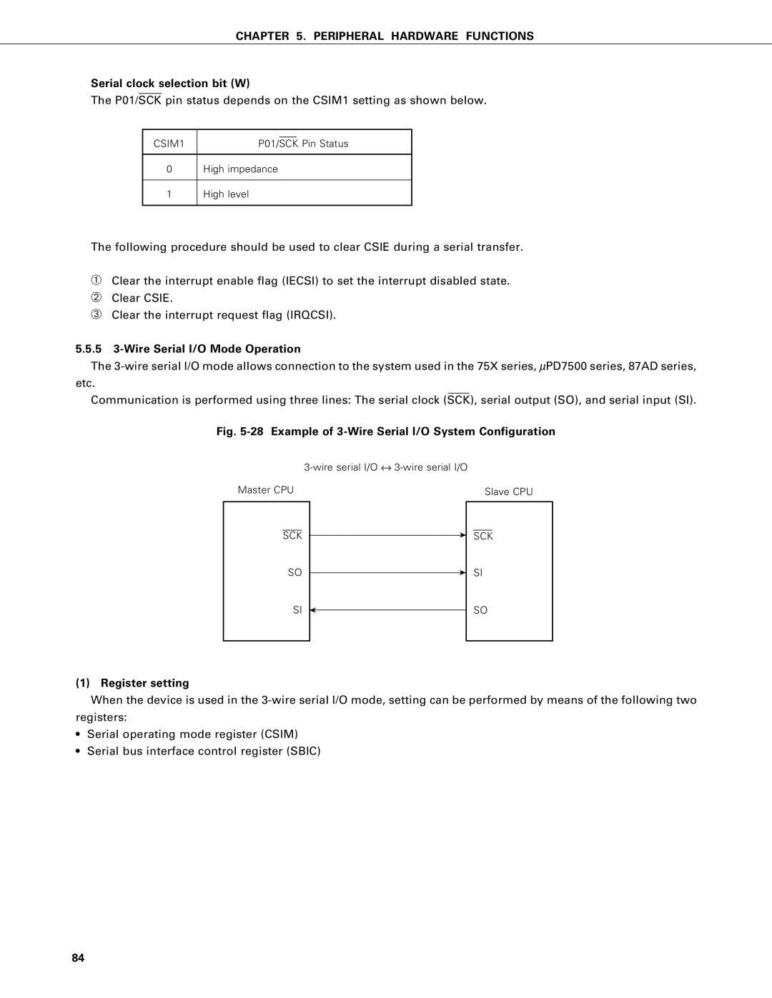
Serial interface operating mode selection bit W
Serial clock selection bit W
Csie
Signal from address comparator R
Csie CSIM1
MOV CSIM, XA
SET1 Csie
Csie CSIM3
Cmdd Reld Cmdt Relt
FE2H
Acknowledge trigger bit W
Command trigger bit W
Command detection flag R
Bus release detection flag R
Acknowledge detection flag R
Busy enable bit R/W
BUSY/ACK
SIO
CLK
Slave address detection
Error detection
See 5.5.6 8 Error detection for details
Slave address register SVA
Csie C0I WUP CSIM3 CSIM1 Csim
Register setting
28 Example of 3-Wire Serial I/O System Configuration
5 3-Wire Serial I/O Mode Operation
Remarks Figuer Apply to fXX = 4.19 MHz operation
Shift register data do not match Register data match
FE2H Bsye Ackd Acke Ackt Cmdd Reld Cmdt Relt Sbic
Command trigger bit
Communication operation
29 3-Wire Serial I/O Mode Timing
Relt Cmdt
Serial Clock Selection and Use in 3-Wire Serial I/O Mode
Signals
Serial clock selection
Start of transfer
Data transfer order
SCK SO/SB0
Wire serial I/O mode applications
MOV XA, Tdata
MOV SIO, XA
MOV RDATA, XA
MOV XA, Tdata SIO, XA
Iecsi
MOV XA, Tdata XCH XA, SIO
SB0 SCK
SBI Mode Operation
+ VDD
CPU SB0 SCK
SBI functions
Address/command/data differentiation function
Acknowledge signal ACK control function
Busy signal Busy control function
SB0 D0 ACK Busy
SBI definition
SB0 ACK
SB0 C0 ACK Busy
SCK H SB0
Bus release signal REL
Command signal CMD
SCK H
37 Slave Selection by Address
Address
Data
Command & data
SCK SB0 ACK
Acknowledge signal ACK
SCK SB0 ACK Busy
Busy signal BUSY, ready signal Ready
100
101
102
103
104
105
Serial Clock Selection and Use in SBI Mode
SIO SCK
RELT, CMDT, Reld & Cmdd Operation Slave
106
SIO SCK SB0 Relt Cmdt Reld Cmdd
107
44 Ackt Operation
108
When Acke is set after completion of transfer
When Acke = 0 on completion of transfer
When Acke = 1 interval is short
SCK SB0 Bsye ACK
When ACK signal is output after 9th SCK clock interval
109
SCK SB0 ACK Ackd
SB0 Ready
110 Signals in SBI Mode
SCK Cmdd
SB0 ACK Ready
REL CMD
111
Pin Configuration Diagram
Pin configuration
113
Address match detection method
Use of slave address register SVA
Hardware
114
Chapter
Peripheral
115
50 Command Transmission from Master Device to Slave
51 Data Transmission from Master Device to Slave Device
116
117
52 Data Transmission from Slave Device to Master Device
118
Points to note concerning SBI mode
119
SBI mode application
Serial bus configuration
120
Description of commands Command types
Ii Communication procedure
121
Iii Command formats
➀ Read command
➁ WRITE, END and Stop commands
ACK Stop
122
MSM
MSB LSB
➂ Status command
123
Status
Chgmst
Reset command
➄ Chgmst command
124
125
Iv Error occurrence
Errors generated on the slave side
Errors generated on the master side
Interrupt Functions
127
VENT1 Gotobt VENT2 GOTO0
Interrupt Functions Interrupt Source Types and Vector Table
Interrupt Request Source Types
VEN T1 GOT OBT
IE0
Interrupt request flag & interrupt enable flag
Interrupt Request Flag Setting Signal
Example EI
130
External interrupt input pin hardware
INT2 Input Noise Elimination
INT0 Noise Elimination Circuit Input/Output Timing
FB2H
Interrupt master enable flag IME
132
FB4H IM03
133
Interrupt status flag
IST0 Interrupt Servicing Status
IME=1
Interrupt Functions Interrupt Sequence
YES
Interrupt INTxxx generation
136
EI Iecsi
Interrupt Functions Interrupt Applications
Interrupt enabling/disabling
➄ Reti
Example using INTBT, INT0 falling edge active, and Intcsi
138
CLR1 IRQ0
➃ EI Iecsi Reti
139
EI IE0
➂ Intcsi Reti
INT0 Intcsi ➁ Reti
Pending interrupt execution
140
Standby Function
Stop mode
Halt mode
Standby Mode Operation States
Standby Function Standby Mode Setting and Operation States
Halt mode reset by interrupt generation
Standby Function Standby Mode Reset
Stop mode reset by Reset input
Halt mode reset by Reset input
Halt
144
IME =
Standby Function Operation After Standby Mode Reset
Reset at Power-on
Reset Signal Acceptance
OFF
State of Hardware after Reset
147
148
Architecture and Memory MAP
Example A0
Instruction SET Special Instructions
Bit Manipulation Instructions
Stack Instructions
Adds Addc
Base Correction Instructions
Base correction at addition
Addc
Operation description legend
Instruction SET Instruction SET and ITS Operation
Operation identifier and description
152
Description of addressing area field symbols
Description of machine cycle field
XOR
Movt XA, @PCXA
Adds
Addc
154
NOP
Instruction Group
Instructions
155
Iebt Iecsi IE0 IE2
Description of operation code symbols
Instruction SET Operation Code of Each Instruction
Bit manipulation addressing operation code
SET CLR SKT Not
Rorc Not Incs
Halt Stop NOP
RET Rets Reti Push POP
MOV HL, #5FH
Instruction SET Instruction Functions and Application
Move Instructions
MOV A, #0BH
160
MOV XA, 20H
161
Loop XCH
MOV XCH
02FFH
Table Reference Instructions
Table data on that
162
163
Arithmetic and Logic Instructions
See section
164
Or A, @HL
165
Rorc a
166
Incs reg
167
SKE reg, #n4
168
Carry Flag Operation Instructions
169
Bit Manipuration Instructions
170
SKF mem. bit
171
BR addr
172
Subroutine Stack Control Instructions
173
Push rp
174
Interrupt Control Instructions
175
Input/Output Instructions
176
Halt
177
178
179
Language Processor
Prom Writing Tools
180
Debugging Tools
IBM PC/AT
Development Tool Configuration
181
182
183
Port
184
Irqcs
Pmgb Cmdd