Section | Appendix A. EX 1.0 Feature Update |
|
|
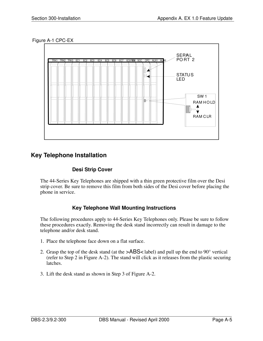
Figure |
|
|
|
|
|
|
|
|
|
|
|
|
|
|
|
|
|
|
|
|
|
|
|
| SERIAL |
TRK1 TRK2 TRK3 | EC1 | EC2 | EC3 | EC4 | EC5 | EC6 | EC7 | EC8 EC/TRK SCC | CPC | AUX1 | AUX2 | PO RT 2 |
|
|
|
|
|
|
|
|
|
|
|
| STATU S |
|
|
|
|
|
|
|
|
|
|
|
| LED |
|
|
|
|
|
|
|
|
|
|
|
| SW 1 |
|
|
|
|
|
|
|
|
|
|
|
| RAM H O LD |
|
|
|
|
|
|
|
|
|
|
|
| RAM C LR |
Key Telephone Installation
Desi Strip Cover
The
Key Telephone Wall Mounting Instructions
The following procedures apply to
1.Place the telephone face down on a flat surface.
2.Grasp the top of the desk stand (at the >ABS< label) and pull up the end to 90° vertical (refer to Step 2 in Figure
3.Lift the desk stand as shown in Step 3 of Figure
DBS Manual - Revised April 2000 | Page |
