Chapter 4. Trunks and Lines | Section |
|
|
Installation
1.Install the
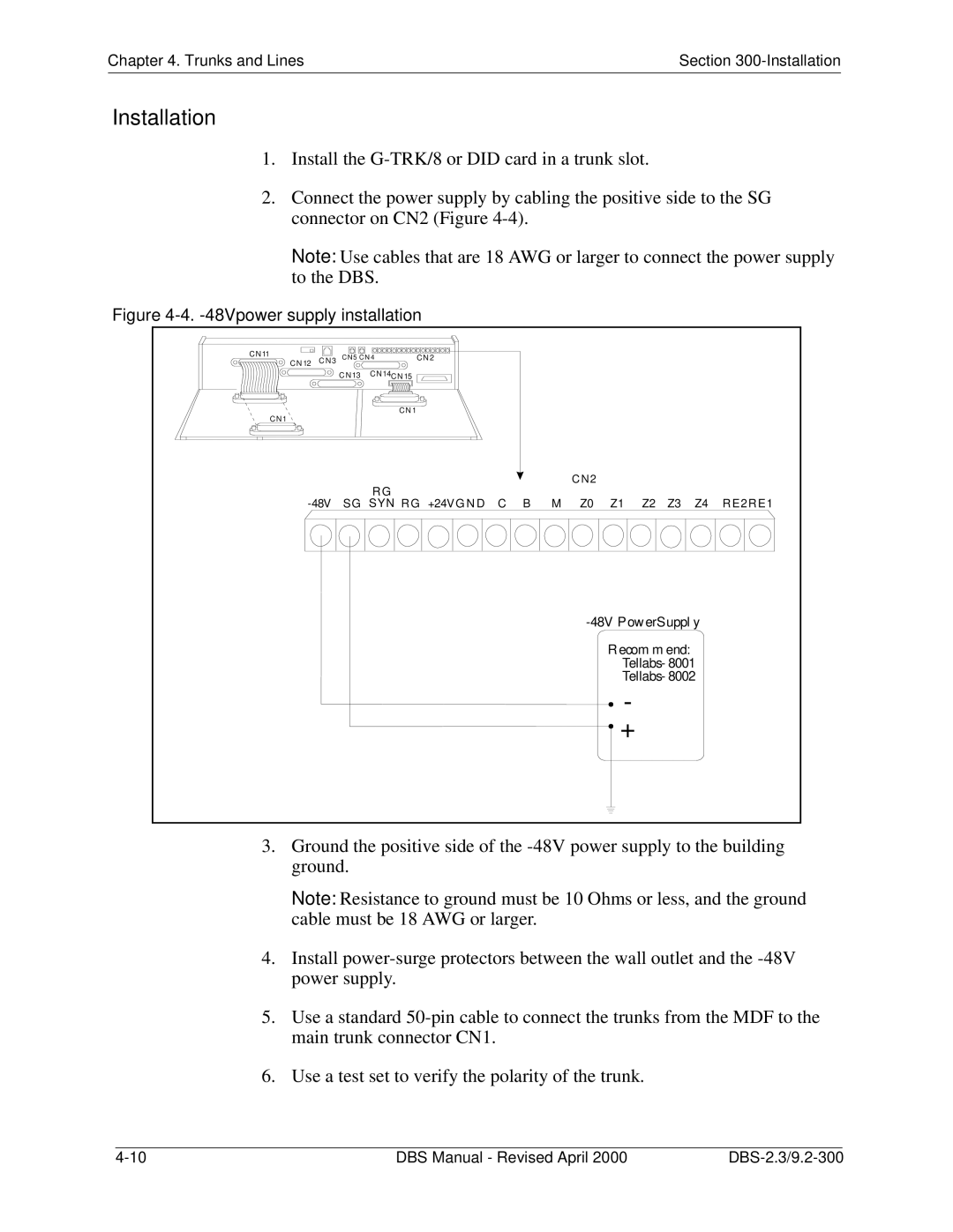
2.Connect the power supply by cabling the positive side to the SG connector on CN2 (Figure
Note: Use cables that are 18 AWG or larger to connect the power supply to the DBS.
Figure |
|
|
|
|
|
|
|
|
|
| |||
C N11 | C N 5 C N 4 |
| C N 2 |
|
|
|
|
|
|
|
|
| |
C N 12 C N 3 |
|
|
|
|
|
|
|
|
|
| |||
| C N 13 | C N14 C N 15 |
|
|
|
|
|
|
|
|
|
| |
|
|
| CN 1 |
|
|
|
|
|
|
|
|
|
|
C N1 |
|
|
|
|
|
|
|
|
|
|
|
|
|
|
|
|
|
|
|
|
| C N2 |
|
|
|
|
|
|
| RG |
|
|
|
|
|
|
|
|
|
|
|
SG | SYN | R G | +24V G N D | C | B | M | Z0 | Z1 | Z2 | Z3 | Z4 | R E2 RE1 | |
|
|
|
|
|
|
|
|
| |||||
|
|
|
|
|
|
|
|
| R ecom m end: |
|
| ||
|
|
|
|
|
|
|
|
|
|
| |||
|
|
|
|
|
|
|
|
|
|
| |||
|
|
|
|
|
|
|
|
|
| - |
|
|
|
|
|
|
|
|
|
|
|
| + |
|
|
| |
3.Ground the positive side of the
Note: Resistance to ground must be 10 Ohms or less, and the ground cable must be 18 AWG or larger.
4.Install
5.Use a standard
6.Use a test set to verify the polarity of the trunk.
|
|
|
|
DBS Manual - Revised April 2000 | |||