Chapter 3. Cabinet Installation | Section |
|
|
Installation for the DBS 40
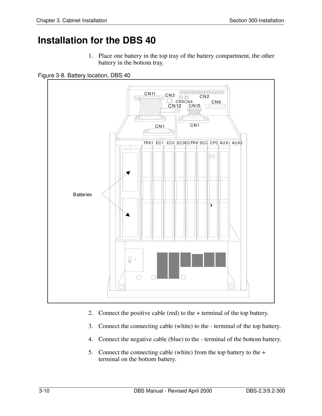
1.Place one battery in the top tray of the battery compartment, the other battery in the bottom tray.
Figure 3-8. Battery location, DBS 40
CN 11 |
| C N 3 | CN 2 |
|
|
|
| ||
|
|
|
| |
|
| CN 5 CN 4 | CN 6 | |
|
| CN 12 | C N15 |
|
| C N 1 |
| C N1 |
|
|
|
|
| |
TRK1 | EC1 | EC 2 EC 3 EC /TR K SC C | C PC AU X1 AUX2 | |
Batteries |
|
|
|
|
2.Connect the positive cable (red) to the + terminal of the top battery.
3.Connect the connecting cable (white) to the - terminal of the top battery.
4.Connect the negative cable (blue) to the - terminal of the bottom battery.
5.Connect the connecting cable (white) from the top battery to the + terminal on the bottom battery.
|
|
|
|
DBS Manual - Revised April 2000 | |||
