Section | Chapter 4. Trunks and Lines |
|
|
Connect the test set across the tip and ring of the trunk to be tested. With the test set in the “monitor” position, apply ground to the ring side of the trunk.
If you hear dial tone, the polarity of the trunk is okay, and you can switch the test set to the “talk” mode to test the voice path.
If you do not hear dial tone, ground the tip side of the trunk. If you receive dial tone when grounding the tip side, polarity is reversed.
T1 Interface
Guidelines
Read the following guidelines before beginning T1 installation. Installation instructions begin on page
Hardware Requirements
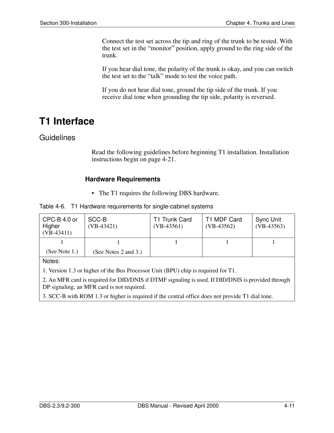
• The T1 requires the following DBS hardware.
Table 4-6. T1 Hardware requirements for single-cabinet systems
| T1 Trunk Card | T1 MDF Card | Sync Unit | |
Higher | ||||
|
|
|
| |
|
|
|
|
|
1 | 1 | 1 | 1 | 1 |
(See Note 1.) | (See Notes 2 and 3.) |
|
|
|
|
|
|
|
|
Notes: |
|
|
|
|
1. Version 1.3 or higher of the Bus Processor Unit (BPU) chip is required for T1.
2. An MFR card is required for DID/DNIS if DTMF signaling is used. If DID/DNIS is provided through DP signaling, an MFR card is not required.
3.
DBS Manual - Revised April 2000 |
