Section | Chapter 4. Trunks and Lines |
|
|
Loop-Start Trunks
Guidelines
•Two versions of the
•The following procedure covers
•For pinouts and color codes for the main trunk connector, see Table
Installation
Installation without Caller ID
1.If installing
a.Remove the cover from the
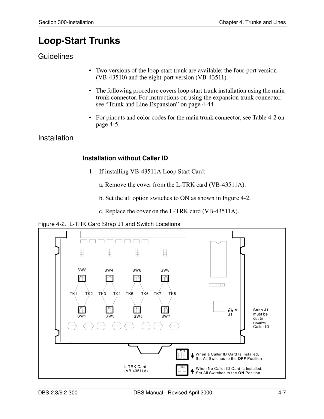
b.Set the all option switches to ON as shown in Figure
c.Replace the cover on the
Figure 4-2. L-TRK Card Strap J1 and Switch Locations
| SW2 | SW4 |
| SW6 | SW8 |
|
| ||
| ON | ON |
|
| O N |
| ON |
|
|
TK1 | TK2 | TK3 | TK4 | TK5 | TK6 | TK7 | TK8 |
|
|
| ON | ON |
|
| O N |
| ON |
| Strap J1 |
|
|
|
|
|
|
|
|
| |
| SW1 | SW3 |
| SW5 |
| SW7 | J1 | must be | |
|
|
|
| cut to | |||||
|
|
|
|
|
|
|
|
| |
|
|
|
|
|
|
|
|
| receive |
|
|
|
|
|
|
|
|
| Caller ID |
ON
ON
![]() When a Caller ID Card Is Installed,
When a Caller ID Card Is Installed, ![]() Set All Switches to the OFF Position
Set All Switches to the OFF Position
When No Caller ID Card Is Installed, Set All Switches to the ON Position
DBS Manual - Revised April 2000 |