Section | Chapter 4. Trunks and Lines |
|
|
Trunks
Trunk Connectors
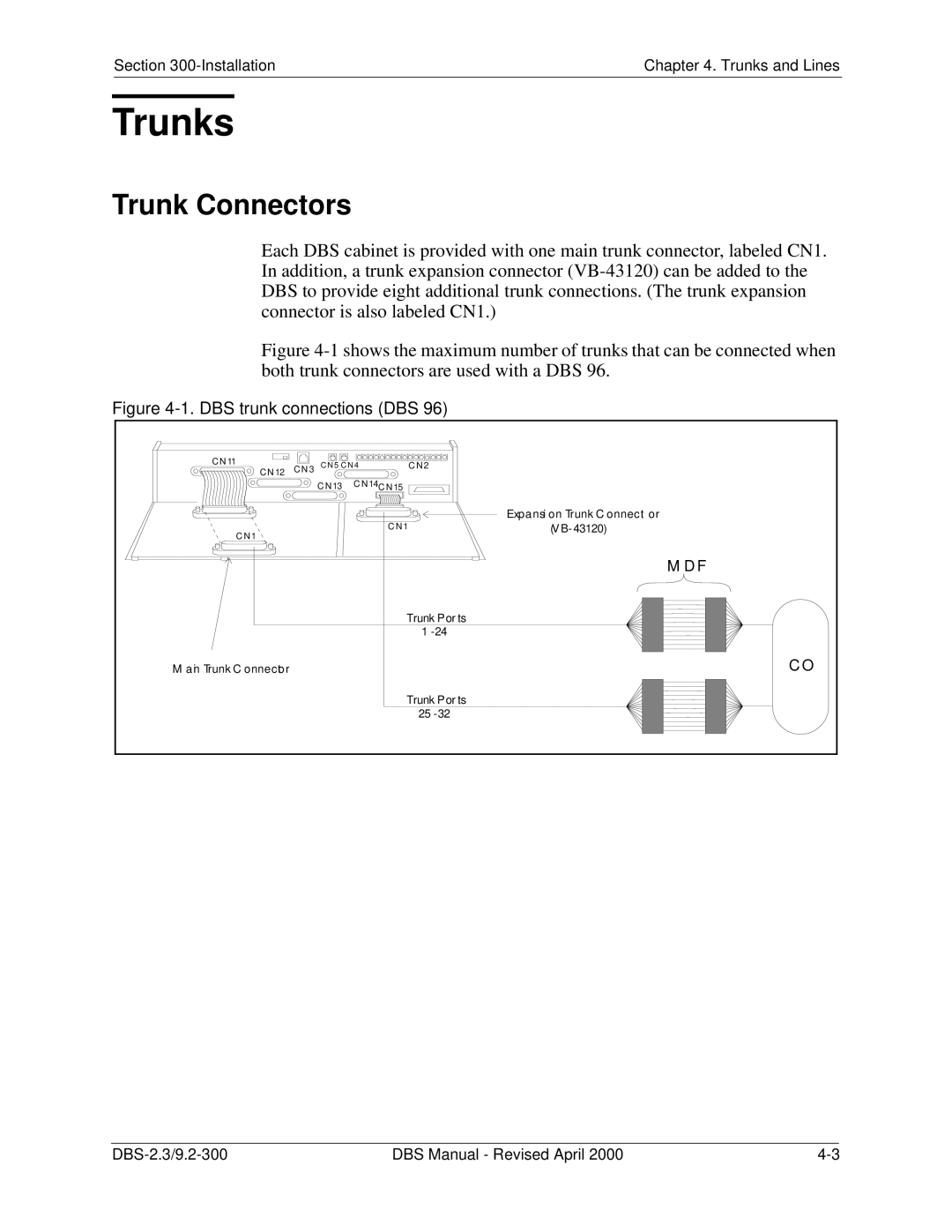
Each DBS cabinet is provided with one main trunk connector, labeled CN1. In addition, a trunk expansion connector
Figure 4-1 shows the maximum number of trunks that can be connected when both trunk connectors are used with a DBS 96.
Figure 4-1. DBS trunk connections (DBS 96)
C N 11 | C N 5 CN 4 | C N 2 | |
C N 12 C N 3 | |||
| C N 13 | C N 14 C N 15 |
|
|
|
| Expansion Trunk C onnector |
C N 1 |
| C N 1 | (V |
|
|
| |
|
|
| M D F |
|
|
| Trunk Ports |
|
|
| 1 |
M ain Trunk C onnector |
|
| C O |
|
|
| Trunk Ports |
|
|
| 25 |
DBS Manual - Revised April 2000 |
