Panasonic
Page
Table of Contents
Peripheral Equipment
Trunks and Lines
Double-Cabinet Systems
Specifications
Index-1
Appendix B CPC-AII/B 8.0 Updates
List of Figures
Smdr Format for CPC-AII and CPC-B Version 3.1 or higher
List of Tables
List of Tables Installation
Chapter Title Purpose
About This Manual
Purpose
Related Information
Page
General Requirements
Requirements
Model Numbers
FCC Requirements
OPX
Specification
RJ21X
RJ48C
Did Requirements
T1 Requirements
Environmental Requirements
Cleaning
Page
System Overview
DBS Manual Revised April DBS-2.3/9.2-300
DBS cabinet DBS 96 shown
Cabinet Description
Trunk, line, and peripheral connections
Configurations
Doorbox Equipment Trunk
Expansion Connectors
Printed Circuit Cards
Printed Circuit Cards and Other Quantity Equipment DBS
API
Card Type Acceptable Slots
Processor Description
Feature CPC/SCC Requirements
Page
Cabinet Installation
DBS Manual Revised April DBS-2.3/9.2-300
Guidelines
Installation
Wall-Mounting the Cabinet
Cabinet mounting bracket
Cabinet ground screw
Grounding
SCC CPC
Card Installation
TRK DEC
CPC Strap S1
Printed circuit card installation
System Battery Backup Part No
Battery Backup
Battery location, DBS
Installation for the DBS
Battery tray, DBS 72
Installation for the DBS 72
2650-2P
11. Wall-mount adaptor removal
Key Phone Wall Mounting
12. Wall-mount adaptor replacement
14. Desk stand removal for Dslt wall mounting
Dslt Wall Mounting
15. Desk stand attachment for Dslt wall mounting
System Initialization
17. CPC memory clear switch
Test Phone
18. Test telephone connection
Page
Trunks and Lines
DBS Manual Revised April DBS-2.3/9.2-300
Trunks
Trunk Connectors
System Type Main Trunk Numbers Expansion Trunk Numbers
Trunk Connector Pinouts
Pinouts and trunk numbers for the main trunk connector
Pinouts and trunk numbers for trunk expansion connector CN1
Loop-Start Trunks
Installation without Caller ID
Attaching Caller ID Card to the L-TRK Card
Installation with Caller ID
Manufacturer Model Number Rating
Ground Start and did Trunks
48Vpower supply installation
Hardware Requirements
T1 Interface
T1 Hardware requirements for double-cabinet systems
Maximums
System Size EC/TRK Slot Usage for T1 Master Slave
Trunk Assignments for Single-Cabinet Systems
Trunk Channel T1 Fractional T1 Number Using Using 8 Channels
System Size Master Slave
Trunk Assignments for Double-Cabinet Systems
Trunk Number Master Cabinet Slave Cabinet
Trunk Number Master Cabinet Slave Cabinet
Trunk Number Master Cabinet Slave Cabinet
Trunk Number Master Cabinet Slave Cabinet
If you are installing Use this procedure
Connector 4 CN4 strapping, Sync Unit
Installing a T1 in a Single Cabinet
Attach the Sync Unit to the CPC-B card
T1 MDF card installation
To 150 ft 150-450 ft 450-655 ft
Distance from the DBS to the CSU
RJ48 pinouts, CN1 connector
10. T1 cabinet connections, single-cabinet installation
Installing T1 in a Double Cabinet with the T1 in the Slave
Slave C abinet
Installation Trunks and Lines
Lock Sync Able VB-43564
Lines
Extension Connectors
Extension Connector Pinouts
20. Pinouts and color codes for extension connector CN12
21. Pinouts and color codes for extension connector CN13
22. Pinouts and color codes for extension connector CN14
GN-WH
Analog Extensions
14. SLT ringer box installation
Ringer box installation with the DBS 72 and DBS
15. EMI filter installation DBS 40 only
Guidelines
Digital Extensions
16. DSS/72 connection using one cable with two pairs
Installation
EM/24
Trunk and Line Expansion
Expansion connector
18. Trunk or extension expansion
Page
Peripheral Equipment
DBS Manual Revised April DBS-2.3/9.2-300
Local Terminal or Smdr Device
Pin Signal Name Description
RS-232C connection
Smdr Format for CPC-AII and CPC-B Version 3.1 or higher
Remote Administration Interface RAI
RAI connection
To route the music from Do this
Background Music/Music-On-Hold
VR1 VR2 VR6
Variable Resistor Purpose
VR1 VR5
Off-Premises Adaptor OPX
Mount the OPX Adaptor to the wall
Installing an OPX Station Through a Central Office
OPX installation
Paging
External Page Zone Installation
External zone paging installation
SG SYN
External General Page/UNA Installation
External Ringer UNA Device
External ringer UNA device installation
Power Failure Unit
10. Cable punch-out plate, Power Failure Unit
11. Power Failure Unit PFU installation
OFF=One message up to 32 seconds
Voice Announce Unit VAU
OFF=DBS and DBS
ON=80 ms
Dtmf Detection Timer
Switch Function
Block Switch
12. Cable punch-out plate, Voice Announce Unit
Digits
BK R G Y
Dial * 97
Recording and Playing Messages
Dial * 98
Door Sensors
Door Box Adaptor Trunk Port
If you use Adaptor uses
Requirements
15. Cable punch-out plate, Door Box Adaptor
Door Opener Contact Short Occurs During Trip of Relay
Guidelines
Door Box Adaptor Extension Port
Contact Ratings for
Connect the Door Box and door opener to the Door Box Adaptor
Mount the Slta to the wall see Figure
Single Line Telephone Adaptor
11. Maximum distances for Slta installation
21. Slta installation
Double-Cabinet Systems
DBS Manual Revised April DBS-2.3/9.2-300
Guidelines
DBS 40 Master
DBS 40 Slave
TRK1 EC1 EC2 EC3 EC/TRK SCC CPC AUX1 AUX2
MFR CBL-S
TRK1 TRK2 EC1 EC2 EC3 EC4 EC5 EC6 EC/TRK SCC CPC AUX1 AUX2
DBS 72 Master
TRK EC1 EC2 EC3 EC4 EC5 EC6 SCC CPC AUX
DBS 72 Slave
Sccb Cpcb API CBL-M
TRK EC1 EC2 EC3 SCC CPC AUX
DBS 96 Master
TRK EC1 EC2 EC3 EC4 EC5 EC6 EC7 EC8 SCC CPC AUX
TRK33-40 TRK41-48 EXT73-80 EXT81-88 EXT89-96 EXT97-104
Slot usage for two-cabinet systems, DBS 96 to DBS
MFR CBL
Strap 3, MFR card
Installation
Double-cabinet installation
DBS40 OFF DBS72 DBS96
System Combinations Switch Settings
Specifications
DBS Manual Revised April DBS-2.3/9.2-300
Electrical Characteristics
Environmental Conditions Requirements
Physical DBS Characteristics Dimensions H x W x D in inches
Weight lbs
Cabinet Installation DBS 40 + DBS All Other Combinations
Resource Maximums
Toll Restrictions
Resource Maximums Conference circuits
Hunting
Least cost routing
Description Quantity DBS Phones
Resource Maximums Paging
Speed dial
Trunk Queuing
Printed Circuit Cards
Description Quantity DBS Phone Options
Description Quantity DBS Expansion Connectors
Description Quantity
AEC
Doorbox Equipment Extension Port
Doorbox Equipment Trunk Port
Distance from
Cabling Specifications
Loop Type and Resistance Cable Gauge Maximum Cabling
Length in Feet
Smdr
Communication Parameters
Channel Speed
Port Parameters
Level Distortion
Signaling Characteristics
Internal Tones SLTs
Tone Characteristics
Tone Name Frequency Timing seconds CO Call Tones
Internal Tones Key Phones
Digit Frequency Hz
Tone Name Frequency Timing seconds
Page
Compatibility
Appendix a CPC-EX 1.0 Updates
Directory Mode
FF-Key Programming
Smdr Modifications
Key Telephone Wall Mounting Instructions
Desi Strip Cover
Step
Series Enhanced Phone Features
Figure A-5.44-Series Small-Display Phone
DBS-2.3/9.2-300 DBS Manual Revised April A-9
Figure A-6.44-Series Large-Display Phone
DBS-2.3/9.2-300 DBS Manual Revised April A-11
Operation
FF2
FF1
To Program Voice Mailbox Access Codes into the MSG Key
DSS/72 Console Key Arrangement
DSS/72 Key LayoutFF-key num bering
EM/24 Key Arrangement
44-Series EM/24 operates the same as previous models
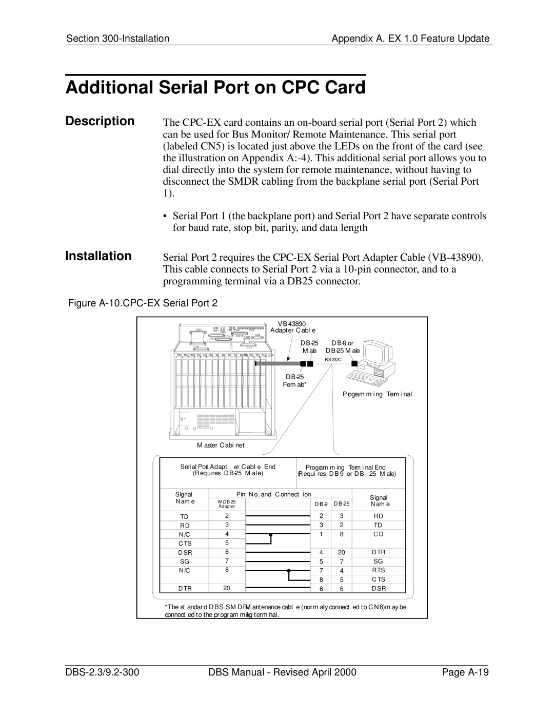
Description Installation
To set Serial Port 1 for Serial Port 2 for
Appendix B CPC-AII/B 8.0 Updates
Contents
Table B-1.44-Series Phones
Enhanced Phone Features
Table B-2.Key to 44-Series Small-Display Phone
Figure B-12.44-Series Large-Display Phone
DBS-2.3/9.2-300 DBS Manual Revised April B-7
Analog Adapter
MSG Message Key
DSS/72 Console Key Arrangement
Figure B-13.DSS/72 Console VB-44320 key layout
DSS #1 DefaultExtension Num bers
EM/24 Key Arrangement
Tapi Support
Figure B-16.Desk Stand Removal
B-16 DBS Manual Revised April DBS-2.3/9.2-300
BGM
Index
DBS
Installation Index
Index-4 DBS Manual Revised April DBS-2.3/9.2-300
RAI
PFU
VAU
DBS-2.3/9.2-300 DBS Manual Revised April Index-7