Section | Chapter 5. Peripheral Equipment |
|
|
Installation
The following procedures describe direct OPX connection and OPX connection through a CO. Order an OL13C circuit for an OPX through a CO. Refer to Figure
Installing an OPX Station Without Going Through a Central Office
1.Remove the cover from the OPX Adaptor.
2.Remove the cable
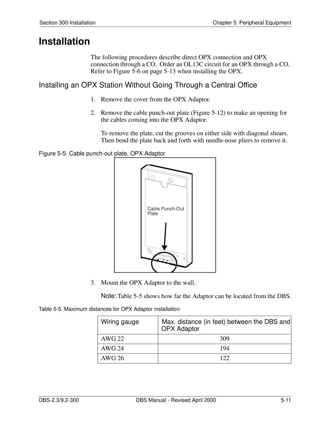
To remove the plate, cut the grooves on either side with diagonal shears.
Then bend the plate back and forth with
Figure 5-5. Cable punch-out plate, OPX Adaptor
3. Mount the OPX Adaptor to the wall.
Note: Table
Table
Wiring gauge | Max. distance (in feet) between the DBS and |
| OPX Adaptor |
|
|
AWG 22 | 309 |
|
|
AWG 24 | 194 |
|
|
AWG 26 | 122 |
|
|
DBS Manual - Revised April 2000 |