Panasonic CPC-EX manual Installing a T1 in a Single Cabinet, Connector 4 CN4 strapping, Sync Unit

Models: CPC-EX

1 204
Download 204 pages 19.37 Kb
Page 69
Image 69

Section 300-Installation

Chapter 4. Trunks and Lines


Installing a T1 in a Single Cabinet

The following instructions explain how to install a T1 in a single-cabinet system. These instructions also apply when a T1 is installed in only the master cabinet of a two cabinet system.

If only one T1 is installed in a two-cabinet system, it must be installed in the cabinet specified in Table 4-8 on page 4-13.

Note: The T1 Interface cannot be used for systems consisting of a DBS 72 connected to a DBS 40.

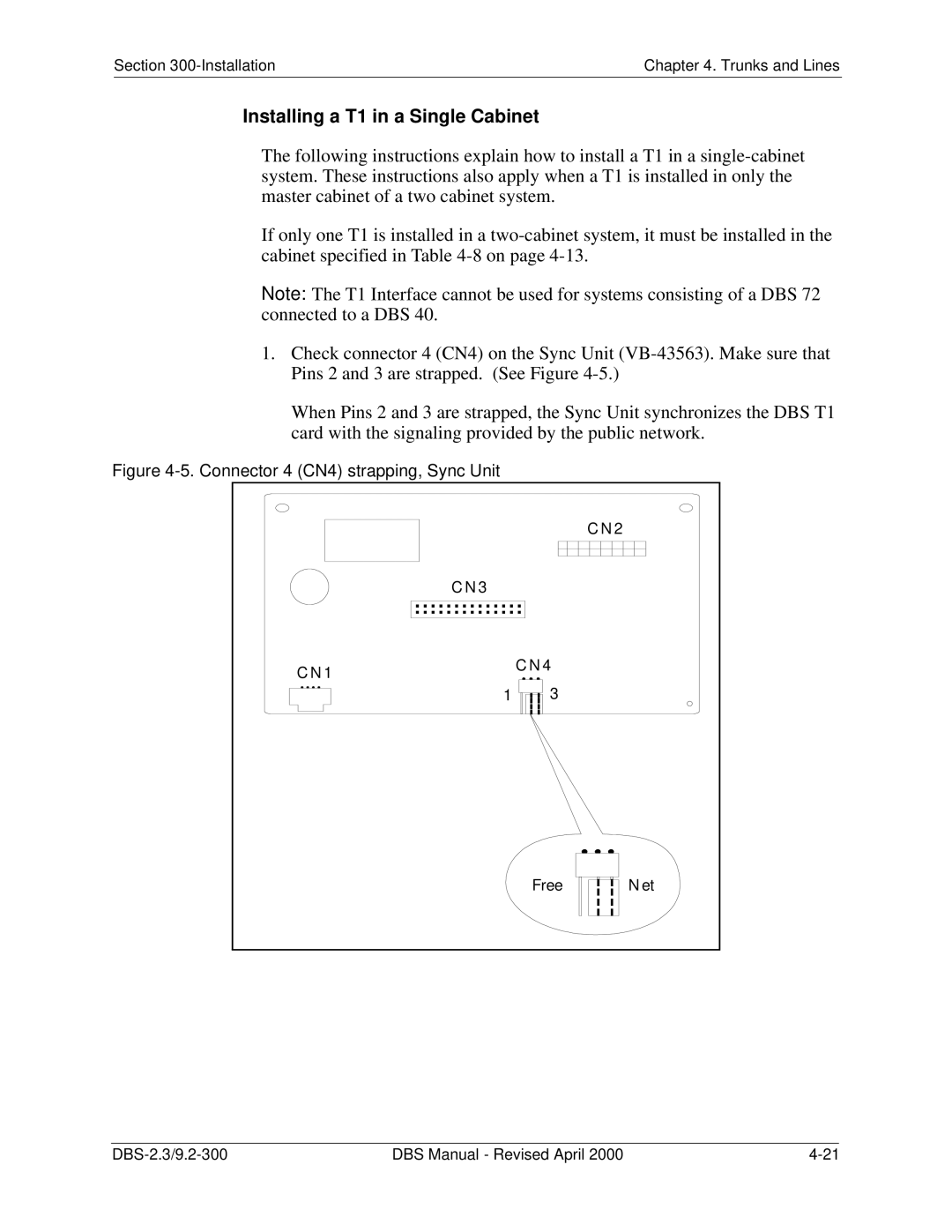
1.Check connector 4 (CN4) on the Sync Unit (VB-43563). Make sure that Pins 2 and 3 are strapped. (See Figure 4-5.)

When Pins 2 and 3 are strapped, the Sync Unit synchronizes the DBS T1 card with the signaling provided by the public network.

Figure 4-5. Connector 4 (CN4) strapping, Sync Unit


C N 2

C N 3


C N 1

C N 4


1

3


Free

N et

DBS-2.3/9.2-300

DBS Manual - Revised April 2000

4-21

Page 69
Image 69
Panasonic CPC-EX manual Installing a T1 in a Single Cabinet, Connector 4 CN4 strapping, Sync Unit