6712FR Refrigerated Sampler
Page
Foreword
Page
6712FR Refrigerated Sampler Safety
Iii
If not avoided, could result in death or serious injury
Understood. While specific hazards may vary according to
Hazard Symbols
Symboles de sécurité
Warnungen und Vorsichtshinweise
6712FR Refrigerated Sampler Safety
Table of Contents
6712FR Refrigerated Sampler
6712FR Refrigerated Sampler Table of Contents
Standard Programming
Extended Programming
Iii
SDI-12 Sondes
Maintenance
Appendix a Menu Flowcharts
Remote Operation
Appendix D Replacement Parts List
Appendix E Accessories List
List of Illustrations
List of Tables
Vii
Viii
Introduction
About This Manual
6712FR Refrigerated Sampler Introduction
6712FR Sampler Features
General Features
Adjustable
Sample Delivery System Features
Standard Programming Features
Extended Programming Features
Option for a Continuous Run- ning Program
Controller, Pump, and Tubing Mechanical Specifications
6712FR Sampler Construction Materials
Material
Controller Electrical Specifications
Typical Repeatability
Power Consumption a
Average Current of Accessories
Controller Software Specifications
Suction Line
6712FR Refrigerated Sampler Physical Specifications
Module Reading Conversions
Dry Weight With
Compressor reaches 221F 105C
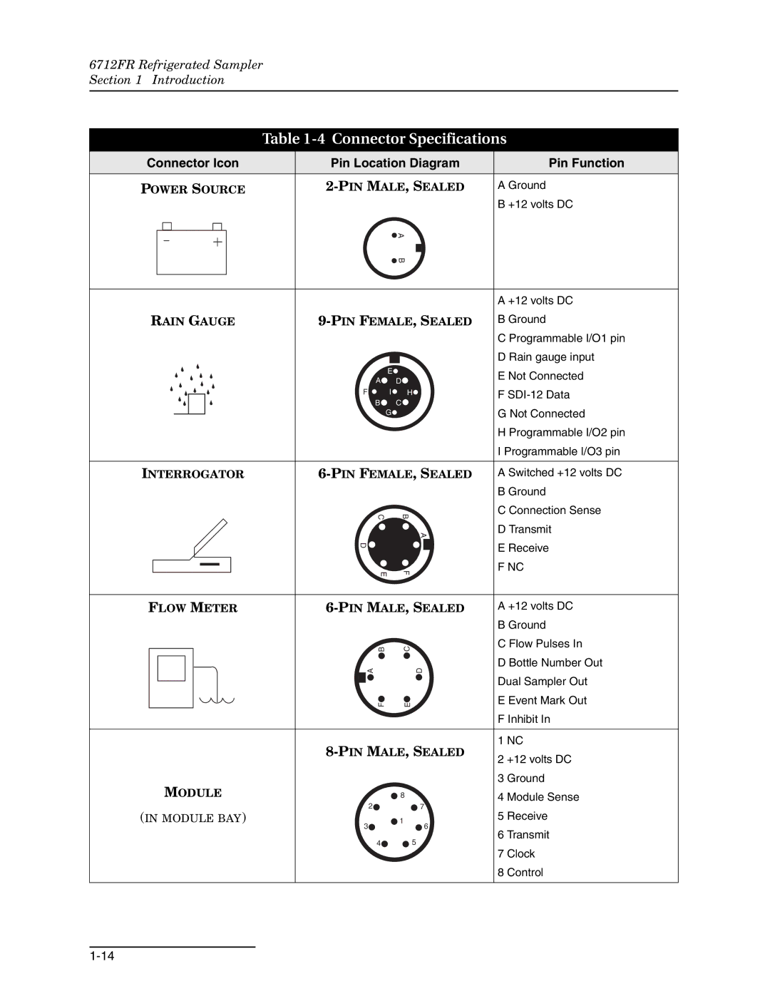
Connector Specifications
Connector Icon
Pin Function
Installation/Preparation
6712FR Refrigerated Sampler Installation/Preparation
Distributor Arm
Discharge Tube
Bottle Kits
Installing Racks
Not rotate the distributor manually. Moving the arm man
Ually damages the distributor drive. If you see any mis
Installing the Bottle Racks
Bottle Kit
Suction Line
Removing Racks
Bottles
Guidelines for Measuring and Cutting the Suction Line
To Pump Tube
Strainer Dimensions Application Maximum Depth
Strainers
Selecting the Right Strainer
How Does the Sampler Work?
Identifying the Sampler Components
Tips for Routing
Suction Line
Rain Gauge Connector
Connecting External Instruments
Intake Placement Positioning a Sampler
Flow Meter
Rain Gauge Connector Icon
Power Source
Connecting Isco Instruments to the Sampler
Connector Icon Connect These Instruments
Rain Gauge
Locking the Sampler
Programming Introduction
Initial Operation
About the Keypad
6712FR Refrigerated Sampler Programming Introduction
Key Name Function
Using Menus and Entering Numbers
Main Menu
Selecting Menu Options Entering Numbers
Quick View Screens
View Screens
Quick View Screen
Clock and Calendar
Setting the Clock and Calendar
Entering Times and Dates
Start Times
Using the Clock Start Time Menu
Menu Screens Site Descriptions and Program Names
Messages
Changing the Site Name
Using Help Notes
Help Notes To see a Help note
Menu Trees
Menu Tree for Standard Programming
6712FR Refrigerated Sampler Programming Introduction
Switching Between Standard and Extended Modes
Standard Programming
Language Selection, Units of Length
Programming Examples
6712FR Refrigerated Sampler Standard Programming
Standard Program Flow-Paced Sampling, Two Bottles Per Sample
Select Enter
Pacing
Trigger Pacing
Bottles Per Sample
Distribution
Sequential
Samples Per Bottle
Sample Distribution
Start Times
Clock Start Time Menu
Delayed Start Screen
Enable/Disable
Sampler
Start Time Diagram
Module. Some module screens will alternate with the sampler
Readings pH and temperature for the pH module level, per
Samplers with an attached module display the module’s
Screens
Interrupting a Running Program
Stop Program Resume Program
Adjust Pacing
Manual Functions Grab Samples
Power Used
Other Functions
Other Functions Menu
Calibrate Volume
Taking a Grab Sample
Calibrating Sample Volumes
For the best results, calibrate the sampler after it’s
Operating the Pump
Operating the Pump
Moving the Distributor Arm
Moving the Distributor Arm
Reports
Collecting Reports
Viewing the Data
Configuring Reports
Viewing Data
Program events include such items as sample events, program
Enables and disables, power losses, and so on. -3lists each
Gramming. When recording four or more sonde parameters,
As the Sampling Results report
Reports Program Events, Source Codes, and Error Codes
Error Codes
Source Codes
Site Description FACTORY051 Units Selected
Report Sampling Results
Sampler ID#
Sampler
Report Summary
System IDs
Programming for 700 Series Modules
Programming Example With 730 Module Installed
17a 17b
Programming Example With 750 Module Installed
Flowmeter
Extended and Standard Mode One-Part and Two-Part Programs
Extended Programming
Selecting a Stored
Programs
6712FR Refrigerated Sampler Extended Programming
Program
Selecting a Stored Extended Program
6712FR Refrigerated Sampler Extended Programming
Sampling
Storm Water Runoff Sampling
This screen will appear briefly
FLOW-INSERT
TWO-PART Program
Above SET Point
Select Flow Module Volume Enter
Select YES Select SET Point Enter
Suction Head
Rinses and Retries
Event Paced Sampling
Select Event Paced
Rate of Change
Clock Times
10.2 Bottles Per Sample
10.6 Time Switching
10.1 Sequential
10.3 Samples Per Bottle
Time Switched
Distribution
Sequential
Flow Proportional Sample Volumes
Flow Module Volume
Calculating Variable Sample Volume Settings
Factors Affecting Flow-Weighted Variable-Volume Samples
Variable-Volume Scenario
Calculations when Using an External Flow Meter
Sampler Enable
Calculations when Using a 700 Series Flow Module
Start Time Diagram for Sampler Enable Settings
Sampler Enable
12.1 Sampler Enable
6712FR Refrigerated Sampler Section Extended Programming
Enabled
Addition to programming enable conditions, extended pro
Once Enabled Stay
Disable
Delay To Start
Dry Period Option Resetting the Sample Interval at Enable
Pause and Resume Screens
Pauses/Resumes
Running Programs
Run Time Screens Interrupting a Running Program
Liquid Detector Enable/Disable
Sampling Reports Other Functions
Software Options
Dual Sampler Mode
Setting Up Dual Samplers
Programming Style Measurement Interval
Adjusting the Display Backlighting
Bottle Full Detect
Event Marks
Event Mark Timing Diagram
Pre-sample and Post-sample Purge Counts
Serial Output Programming the serial
Serial Data Codes
Section Extended Programming
Identifier Parameter Units
Program Lock
Password Protected Functions
Hardware Setup
SDI-12 Sonde Setup Rain Gauge Setup
OFF
Example I/O Pin Programming
Sampler to notify a contact list when an alarm condition
Dialout alarms require the sampler to be equipped with
Factory-installed 2400 baud talking modem, or the external
Alarms are set up through the I/O programming menu, shown
Extended character screen contains a pager option that des
Ignates the phone number as a pager. When programmed as a
After the pager number is dialed, with a three second delay
Between strings
Temperature
Refrigerator
Analog Output
Memory
Interval Changed Download Data NOW Or Lose ALL Data Done
Pressurized Lines Command Driven Operation
Waiting to Sample
Command Driven Sampler Responses
= Waiting to Sample
11 = no Distributor 12 = Sample in Progress
SDI-12 Sondes
SDI-12 Data Parameters
6712FR Refrigerated Sampler SDI-12 Sondes
SDI-12 Sonde Parameters
Connecting an Isco Ready Sonde
Isco Ready Sondes
Sonde Setup Storing Parameter Data
Connecting Other SDI-12 Sondes
Sonde Calibration and Validation
Calibration
Screens
No SDI-12 Sonde
6712FR Refrigerated Sampler SDI-12 Sondes
Remote Operation
6712FR Refrigerated Sampler Remote Operation
Menu Control
6712 Remote Menu Commands
Menu Command Description
Sampling reports
As complex as a user-developed process control program for
6712 controller will respond to four commands
6712FR Refrigerated Sampler Section Remote Operation
Scada or other systems that directs sample collection
= Power Failed = Pump Jammed
= Distributor Jammed = Pump Latch Open
VSI
Remote Control of Sampler Keypad
Computer Sampler
6712 Remote Phone Commands
Phone Name Description Command
False will be returned
Maintenance
Maintenance Checklist
Cleaning Guidelines
Strainer
Air Filter
Condenser
Vinyl Suction Line
Cleaning Protocols for Priority Pollutants
Isco Glass Sample
Ptfe Suction Line
Maintenance Screens
Set Clock Entering Times and Dates
Setting the Clock and Calendar
Resetting the Pump Counter
Checking and Replacing the Internal Battery
Internal Battery
Diagnostics
Please Wait ‘RAM’ Passed Test ‘ROM’ Passed Test
Replacing the Pump Tube
Checklist For Replacing Pump Tube
Conditions that shorten tube life
Removing and Replacing the Pump Tube
Opening the Controller Case
Replacing the Desiccant
To open the case
Opening the Controller
Replacing the Internal Battery
Battery Status Display
To replace the internal battery
Error Messages
Error Messages
Pump Tube Warning
Temperature Control Box Assembly
Servicing the Refrigerator
Electrical System
LEDs
Thermostat Logic Circuit Board
6712FR Refrigerated Sampler Maintenance
6712FR Refrigerated Sampler Maintenance
Capillary Tube Condenser Coil Evaporator Plate Compressor
6712FR Refrigerated Sampler Maintenance
Appendix a Menu Flowcharts
Figure A-1 6712 Menu Tree for Standard Programming
6712FR Refrigerated Sampler Appendix a Menu Flowcharts
Figure A-2 Standard Programming Programming Screens
T e s
Figure A-5
Figure A-5 Standard Programming Quick View Start Times
Figure A-6 View Report
T e
Figure A-8 Manual Functions Screens
Figure A-9 Extended Programming Programming Screens
Figure A-10 Extended Programming Equipment Setup
Figure A-11 Extended Programming Pacing and Distribution
Figure A-12 Extended Programming Event Conditions
T e s
T a I N T E R V a L
Figure A-15 Extended Programming Quick View Equipment Set-Up
See FigureA-17
From Figure A-16 From Figure A-21
F T W a R E O P T I O N S
Figure A-19 Extended Programming Quick View Software Options
T e s
Figure A-21 Extended Programming Quick View Hardware
T e s
Figure A-24 SDI-12 Sonde Screens
6712FR Refrigerated Sampler Appendix a Menu Flowcharts
Appendix B Material Safety Data Sheets
Section II -- Hazardous Ingredients
Section IV -- Fire Explosion Data
Section VI -- Reactivity Data
Section IX -- Special Precautions
Material Safety Data Sheet
Health Hazard Data
Page
Appendix C General Safety Procedures
Practical Safety Precautions
Hazards
Planning
Adverse Atmospheres
Entering Manholes
Traffic Protection
Falling Objects
Removing the Covers
Lethal Atmospheres in Sewers
Emergencies
Field Equipment
Page
Hazardous Gases
Table C-1 Hazardous Gases
CH 2O
N2O
Sea, bad taste Lassitude Turpentine
Page
Appendix D Replacement Parts List
Replacement Parts Diagrams and Listings
Teledyne Isco, Inc
Page
Page
Page
Page
Locknut
Page
Page
Page
Page
Appendix E Accessories List
Order Information Samplers
Bottle Kits
6712FR Refrigerated Sampler Appendix E Accessories List
Bulk Sets of Bottles with Lids
Pump Tubes, Suction Line, Strainers
Data Collection Devices and Cables
12-Volt Power Sources
Modules, Rain Gauges Interfacing Instruments
SDI-12 Data Acquisition Connect Cables
6712FR Refrigerated Sampler Appendix E Accessories List
6712FR Refrigerated Sampler Appendix E Accessories List
Index
Index-1
6712FR Refrigerated Sampler Index
Index-2
Index-3
Index-4
PBB Pbde
Page
Declaration of Conformity
Page
Rmity
Page
Teledyne Isco One Year Limited Factory Service Warranty