Operation Guide
U T I O N
Nederland Netherlands
Read the following before operating the AW4416
Operating Notes
Handling the CD-R/RW media
Responsibility for loss of data, etc
Storing produced data
Vii
Table of contents
Accessing a screen/page
Signal flow within the AW4416
Top panel
Rear panel Front panel
Preparations for recording
Connections Word clock settings
Recording the first tracks
Overdubbing
Locating to the start/end points A-B repeat
Saving a scene/song
In/out points
Markers
Using AUX send/return to apply an effect
Editing command list
About the internal effects
Inserting an effect into a desired channel
Editing the song name/comment Deleting/copying a song
Saving/loading a song
Importing mixer data of an existing song
About scene memory
Formatting the internal hard disk/external Scsi device
Connections Setting the Port Select parameter
Erasing CD-RW media
About mastering
Checking the included items
Before you begin
Trademarks
Copyright
About the internal hard disk
Installing an internal hard disk
You will need the following items
Installation
Flat cable
Scsi ID of the CD-RW drive
Installing a CD-RW drive
About the CD-RW drives
Installation procedure
Bottom panel CD-R/RW drive cover panel
Bottom panel CD-R/RW drive cover panel Inner cover
Removing the transport protection pad
How to remove the transport protection pad
About external Scsi devices
Attaching an external Scsi device
Manual eject emergency disc removal
Attach a terminator to the last Scsi device in the chain
Connection procedure
About terminators
About Scsi errors
About I/O cards
Installing I/O cards
Please keep the cover and screws you removed in a safe place
Important points you Must observe
Turning the power on or off
Turning the power on
Press the Utility key → F4 key
Setting the internal clock
Shut-down operation
Turning the power off
Vibration during use
Transporting the AW4416
Mixer section
Features of the AW4416
Welcome to the world of the AW4416
Recorder section
CD-RW drive option
Other features
Sampling pad section
AW4416
Signal flow within the AW4416
Input patch
Input
Input channels
Return
Return channels 1/2
Monitor channels
Recorder input patching
Stereo
BUS
Stereo output channel
Digital cascade connections
Oscillator
AUX buses
Buses
Internal effects 1/2
Output patch
CH Direct OUT
Insert Send
When the Track CUE key is on
When the Solo key is on
When the internal metronome function is on
Monitor output/headphone output
Analog input/output section
Partstions and their func
Top panel
Unit section
Work Navigate section
Mixer section
Home key
Fader Mode section
AUX 1-AUX 6 keys
AUX 7/AUX 8 keys
16 key 17-24 key Moni key
Mixing Layer section
Input channels
Stereo output channel
Monitor channels
Stereo output channel Effect return channels 1/2
Input channels No function
SEL select keys
SEL keys, on keys, faders
On key
Faders
Display section
ABS/REL switch
Access indicator
Level meter/counter section
Shift key
Recorder section
Scene Memory section
Automation section
JOG on key
CURSOR/JOG & Shuttle section
DATA/JOG dial
Shuttle dial
Locate section
Transport section
Sampling PAD section
Rear panel
Phantom +48V ON/OFF switch
Input 1/2 XLR jacks
Input 1/2 phone jacks
Input 3-8 phone jacks
Insert I/O 1/2 jacks
Input 8 HI-Z jack
Hard Disk Drive slot
Option I/O slots 1/2
Scsi connector
Phones jack
Digital Stereo in jack
Power switch
To Host connector
AC Inlet connector
MTC OUT connector
CD-RW drive cover
Front panel
Display
User interface of the AW4416
Menu button
Song/scene information
Main screen
Cursor
Tab
Buttons
Knobs/faders/numerical boxes
Level meters/counter
Input Monitor indicator
REC Ready indicator
Level meters
Level meter L/R
Using the controls of the top panel
Accessing a screen/page
Using the mouse
Basic operation of the AW4416
Press the Enter key
Turning a button on/off
Move the pointer to the desired button
Click the left or right button of the mouse
Rotate the DATA/JOG dial to edit the value
Editing the value of a fader/knob/numerical box
Directly click one of the additional function buttons
Using the additional function buttons
A screen where the symbol is displayed, click the symbol
Inputting text
Using the controls of the tab
Input the remaining characters in the same way
Cancel button
Text input box
OK button
Click a character button
Press the SEL key of the channel you wish to control
Selecting channels
HI-MID LO-MID LOW
If the mixing layer is 17-24 RTN
If the mixing layer is
If the mixing layer is Moni
Connections
Connections and setup
Slot 1 1/2-7/8 Slot 2 1/2-7/8
Word clock settings
Press the Setup key → F4 key
AW4416 Word clock master
Using the AW4416 as the word clock master
Wclk
INT
Word clock slave
Using a digital MTR as the word clock master
AW4416 Word clock slave
After selecting the desired button, press the Enter key
Using a DAT recorder as the word clock master
Connections and start-up
RecordingAW4416 on
Preparations for recording
Recording on the AW4416
Press the Song key → F1 key
Creating a new song
Recbit
Tip
Press the Home key → F1 key
Recording the first tracks
Set the input level
Input Patch
Input y→x x=odd number, y=even number
Reset Both
Input x→y x=odd number, y=even number
Press the PAN key → F1 key
Assign the signals to buses
Level meters/counter section, press REC Track Select keys 1
Set the tracks to record-ready mode
Press the PAN key → F3 key
Make monitor settings
Press the Moni key
Hold down SEL key 1, and press SEL key
Raise the Monitor OUT control/PHONES control
Press the Locate section RTZ key
Let’s record
Tip
Overdubbing
Mixing Layer section, press the 1-16 key → SEL key
Assign the signal to a bus
Press the View key → F1 key
Level meters/counter section, press REC Track Select key
Put the track in record-ready mode
Make monitor settings
Using the four-band EQ
Using EQ and the dynamics processor
Press the DYN key → F2
Using the dynamics processor
Press the F1 key
Let’s overdub
Creating the mix balance of the tracks
Mixdown
Press the Setup key → F3 key
Using the Solo function
Mixdown Solo
Recording Solo
Last Solo
MIX Solo
To defeat the Solo function, press the Solo key once again
Press the AUX 7 key → F2 key
Using the internal effects
Press the Mono key → AUX 7 key
100
Press PAN key → F2 key
Mute groups
Other convenient functions
Fader groups
Automix
Recording the stereo track
102
Press the REC Track Select ST key
Move the cursor to the M mute button and press the Enter key
Level meters/counter section, turn the Track CUE key on
104
Press the Scene Memory section Store key
Saving a scene/song
Saving a scene
Press the Work Navigate section Song key → F1 key
Saving a song
106
Song will be saved
Table of transport key operations
Transport/locateations oper
Shuttle function cue/review opera- tion
Using the Nudge function
Nudge function
110
Nudge time
With the song stopped, press the Utility key → F3 key
Nudge function settings
112
Rollback function
When the song is stopped or playing, press the Roll Back key
To execute the Locate operation, press the Enter key
Locating to a specific point
114
Locating to the zero location of the counter
Setting the zero relative time location
If the counter shows absolute time ABS
If the counter shows relative time REL
116
Locating to the start/end points
Repeat
Setting the A/B points
Performing A-B repeat playback
118
A and B points must be at least one second apart
120
Setting the In point/Out point
In/out points
Locating to a marker
Setting a marker
Markers
122
Press the Track key → F4 key
Adjusting the location of a locate point
124
Deleting a locate point
Deleting an In/Out point or A/B point
Deleting a locate point using the panel keys
Deleting a marker
126
Punch-in/out
This chapter explains how to use punch-in/out
About punch-in/out
Manual punch-in/out → P.128
Connect a foot switch
Make input monitor settings
Manual punch-in/out
Preparations
Manual punch-in/out recording
Following diagram shows the manual punch-in/out procedure
Set the auto punch-in/out points
Auto punch-in/out
Set the pre-roll/post-roll times
130
Press the Utility key → F3 key
Rehearsing and recording with auto punch- in/out
Rehearsing with auto punch-in/out
132
Recording with auto punch-in/out
Patching to the input channels
Press the Setup key → F1 Patch in key
Patching
Input channels
134
Input channels Return channels 1/2
Recorder inputs
Patching to the recorder inputs
136
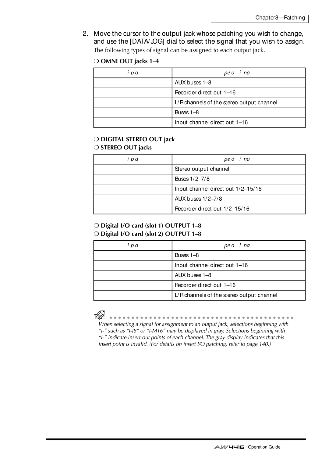
Press the Setup key → F2 Patch OUT key
Patching to the outputs
Digital Stereo OUT jack Stereo OUT jacks
Omni OUT jacks
Patch library
Press the Setup key → F3 Patch Lib key
Storing to the patch library
138
Recalling a patch program
140
Patching input/output jacks to an insert I/O point
Omni 1 Omni
When selecting for an input channel 1-24 or monitor channel
142
Press the Quick REC key
Using the Quick Rec function
144
Record-ready and mute status will be canceled for all tracks
Track structure of the AW4416
Track and virtual track operations
Audio tracks
Bit song
Stereo track
148
Virtual tracks
Press the Track key → F2 key
Switching virtual tracks
Track number
Track name
150
Pairing tracks
152
Editing tracks and virtual tracks
Tracks, parts, and regions
Naming a virtual track
Naming a virtual track or region
Recorder section, press the Edit key → F1 key
Move the cursor to the Track menu and press the Enter key
Move the cursor to the Track button and press the Enter key
154
Move the cursor to the Name menu and press the Enter key
Move the cursor to the Region menu and press the Enter key
Naming a region
Move the cursor to the Name button and press the Enter key
156
Track editing procedure
Pair
Bar graph
TRACK/PART/REGION menus
Parameter setting area
158
Virtual track number
Virtual track editing procedure
Recorder section, press the Edit key → F2 key
160
Track menu
Editing command list
Erase
Copy
162
Part menu
Delete
Move
Name
Region menu
Divide
Trim
Internal effects
Using AUX send/return
About the internal effects
Inserting an effect into a channel
166
Using AUX send/return to apply an effect
Patching
Recalling an effect program from the library
168
Press the AUX 7 → F4 key
Switching between pre-fader and post-fader
170
Adjusting the send level/return level
Adjusting the send level
Inserting an effect into a desired channel
Setup screen Patch in page will appear in the display
Press Moni key → SEL key
Inserting an effect into monitor channel
172
Tip
Press the AUX 8 key → F2 key
Recalling an effect program
174
About songs
Song management
Song structure
Song structure and size
Usable hard disks/song capacity
Work area for audio CD production
Saving the current song
Saving/loading a song
178
Loading a song
Press the Song key → F2 key
Editing the song name/comment
Deleting a song
Deleting/copying a song
180
Press the Song key → F3 key
Move the cursor to the Delete button and press the Enter key
Copying a song
Move the cursor to the Copy button, and press the Enter key
Optimizing a song
182
Importing mixer data of an existing song
Tempo MAP button .....Tempo map
184
Scene MEM. button ....Scene memories
This chapter explains the sampling pads of the AW4416
Sampling pads
About the sampling pads
186
Press the Setup key → F1 key
Assigning the pad outputs to chan- nels
Sampling PAD section, press the Edit pad → F1 key
Assigning a region to a sampling pad
PAD SEL button
Execute button
Use the Cursor keys to move the cursor to select the region
188
Tip
Sampling PAD section, press the Edit pad → F4
Trimming a sample
190
Trim IN/TRIM OUT
Move the cursor to the PAD button, and press the Enter key
Bank/pad number
PAD Size
192
Move the cursor to the PAD button and press the Enter key
Naming a pad
Sampling PAD section, press the Edit pad → F4 key
Move the cursor to the Erase button and press the Enter key
Erasing a pad sample and name
194
Move the cursor to the PAD button and press the Enter key
196
Recording your performance on the sampling pads
Sampling PAD section, press the Edit pad → F5 key
PAD
Parameter value area
Pad tracks
COPY/ERASE menu
Move the cursor to the Copy menu and press the Enter key
Copying a pad performance
198
FR. Start from start FR. END from end
FR. PAD from pad
To PAD
To Start
Execute
200
Interval
Move the cursor to the Erase menu, and press the Enter key
Erasing a pad performance
Start END
202
About scene memory
Scene memory
Parameters included in a scene
About scene numbers
Press the Scene key → F1 key
Storing a scene
204
Tip
206
Recalling a scene
Editing the name of a scene
208
Protecting a scene
Press the Scene key → F4 key
Changing the order of scenes
Scene 01-50 ON/OFF buttons
Scene 51-96 ON/OFF buttons
210
Storing a scene
Using keys to store/recall a scene
Use the / keys to select the store destination scene number
Press the Store key
Press the Recall key
Recalling a scene
212
Automix
What is automix?
Press the Automix key → F2 key
Creating a new automix
214
Press the F4 key
216
Recording the first section
Press the Play key on the top panel to begin song playback
218
Playing back automix
Overwriting events
220
When you are finished, press the top panel Stop key
Press the top panel Play key to begin song playback
While listening to the song, operate the PAN control
Auto REC button will turn on
Automix punch-in/out
Press the top panel Stop key
222
Press the top panel Play key to play back the song
Editing the fader movements
224
Press the Automix key → F4 key
Editing automix off-line
Time
226
Event
Channel
Event currently selected for editing will be deleted
228
Storing an automix
Tip
230
Recalling an automix
Change scenes by remote control
What you can do using Midi
Remote control via MMC
Synchronize with an external device via MTC/MIDI Clock
232
Midi connectors and the to Host connector
Connection to an IBM/PC series computer
Connections
Connection to an Apple Macintosh series computer
IBM/PC series D-SUB9P → mini DIN8P cross cable
234
Setting the Port Select parameter
Press MIDI, and then press the F1 key
Apple Macintosh series 8-pin system peripheral cable
Press the Midi key, and then press the F1 key
Switching AW4416 scenes from an external device
236
Transmit a program change message from the external device
Press the Midi key, and then press the F2 key
Using MTC to synchronize the AW4416 and a Midi sequencer
238
Record or play back the AW4416 song
240
Press the Song key, and then press the F4 key
Press the F2 key
242
Using MMC to control the AW4416
Start playback on your Midi sequencer
244
Backing up and restoring songs
Selecting the backup format
246
Backing up a song
Press the File key → F1 key
TYPE1
Tip
Press the File key → F2 key
Restoring a song
248
You can select multiple songs for restoring
Formatting the internal hard disk/external Scsi device
Disk utilities
250
Press the File key → F3 key
Formatting an external hard disk
Formatting the internal hard disk
Normal normal format
252
Quick quick format
Formatting removable media such as an MO drive
254
Erasing CD-RW media
Stereo tracks that can be mastered
Mastering
About mastering
256
CD-R and CD-RW
CD-R
CD-RW
Disc At Once
Track At Once and Disc At Once
Track At Once
258
Mastering mode settings
Preparations for mastering
Hold down the Shift key and press the F2 key CD Unload
Writing the master
Press the Mastering key
260
Tip
262
Finalizing
Press the CD Play key
Playing CD-R/RW media the CD Play function
264
To stop playback, press the Stop key
266
228
Index
MY4-AD MY4-DA MY8-AD MY8-AE MY8-AT MY8-TD
268
156
Yamaha Corporation