RJ-45 Ports
12
All 12 ports default to adapter mode for connection to a Token Ring hub. Additionally, ports 1 through 4 can be configured to hub mode to allow direct attachment of workstations or servers.
Front Panel LEDs
The LEDs on the front panel of the Switch 2000 TR reflect the current status of the switch. Use Table
Table
LED Name | Color | Indicates |
|
|
|
Packet LEDs | Green | Traffic present |
| Flashing yel- | Error frames present |
| low |
|
Status LEDs | Green | Port inserted |
| Yellow | Partitioned via management |
| Flashing yel- | Auto Error Partition |
| low |
|
| Off | Port not inserted |
Option Slot | Green | Presence of Option card |
Sta- |
|
|
tus/Packet |
|
|
| Flashing green | Activity on link |
Cascade | Green | Cascade connection present |
Status/ |
|
|
Packet |
|
|
|
| The Front Panel | ||
Table | LED States |
|
|
|
|
|
|
|
|
LED Name | Color | Indicates |
|
|
|
|
|
|
|
| Flashing green | Activity on link |
|
|
Power | Green | Power ON |
|
|
| Yellow | RPS w/alarm |
|
|
MGMT | Off | Operation normal |
|
|
| Flashing green | (slow) Software download |
|
|
| Flashing green | (fast) Power On Self Test |
|
|
|
| (POST) |
|
|
| Yellow | POST has failed |
|
|
|
|
|
|
|
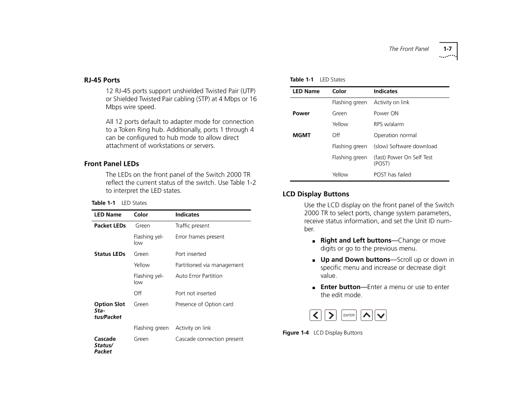
LCD Display Buttons
Use the LCD display on the front panel of the Switch 2000 TR to select ports, change system parameters, receive status information, and set the Unit ID num- ber.
■Right and Left
■Up and Down
■Enter
I
ENTER