Configuration Guidelines
The cable topology rules for Token Ring are shown below:
Media | 4 Mbps | 16 Mbps |
|
|
|
Category 3 UTP | 660 ft/200m | 330 ft/100m |
Category 4, 5 UTP | 1,320 ft/400m | 660 ft/200m |
Type 1 STP | 2,000 ft/600m | 1,000 ft/300m |
|
|
|
Power Supply and Fuse
The Switch 2000 TR automatically adjusts to the sup- plied voltage. The fuse is suitable for either
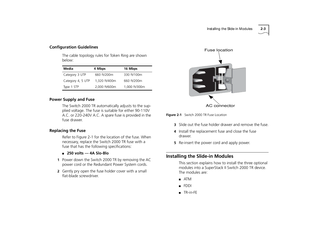
Replacing the Fuse
Refer to Figure
■ 250 volts — 4A Slo-Blo
1Power down the Switch 2000 TR by removing the AC power cord or the Redundant Power System cords.
2Gently pry open the fuse holder cover with a small
Installing the |
Fuse location
AC connector
Figure 2-1 Switch 2000 TR Fuse Location
3Slide out the fuse holder drawer and remove the fuse.
4Install the replacement fuse and close the fuse drawer.
5
Installing the Slide-in Modules
This section explains how to install the three optional modules into a SuperStack II Switch 2000 TR device. The modules are:
■ATM
■FDDI
■