LCD Console Menu Map
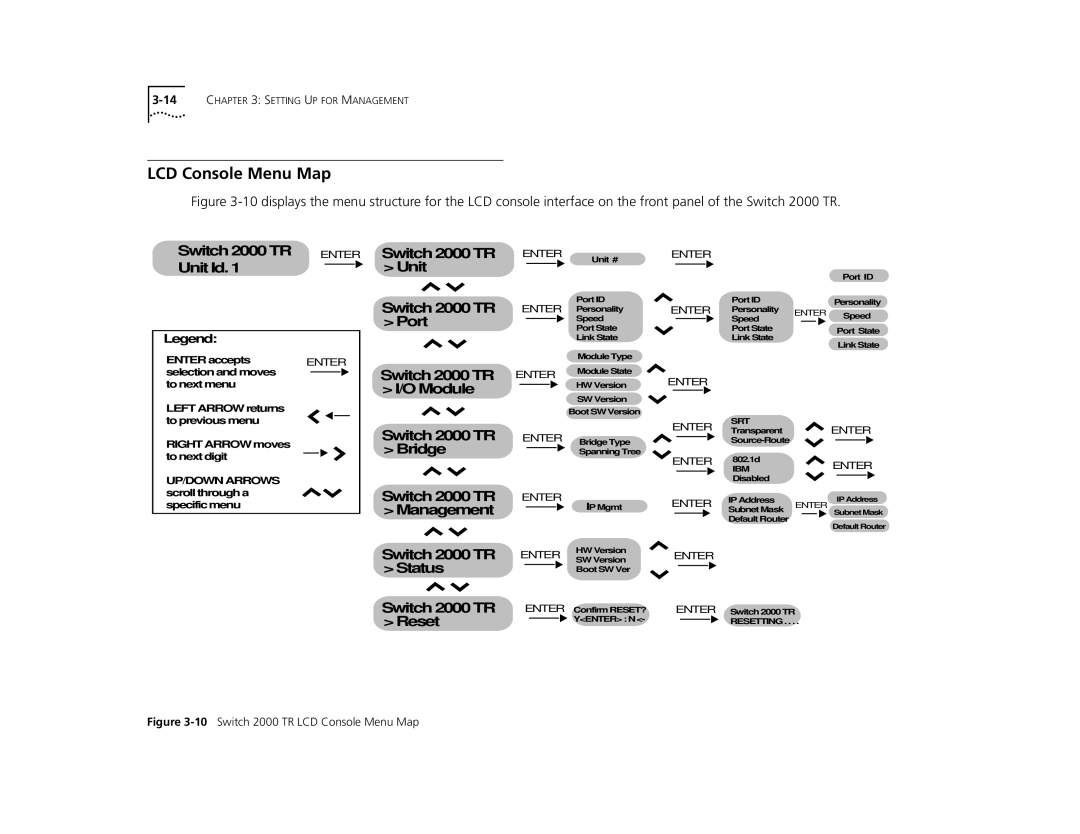
Figure 3-10 displays the menu structure for the LCD console interface on the front panel of the Switch 2000 TR.
SwitchSwitch20002000TRTR ENTER
UnitUnitIdId..11
Legend:
ENTER accepts ENTER selection and moves  to next menu
LEFT ARROW returns to previous menu
RIGHT ARROW moves to next digit
UP/DOWN ARROWS scroll through a specific menu
Switch 2000 TR > Unit
Switch 2000 TR > Port
Switch 2000 TR > I/O Module
Switch 2000 TR > Bridge
Switch 2000 TR > Management
Switch 2000 TR > Status
Switch 2000 TR > Reset
ENTER
Unit #
Port ID
ENTER Personality
Speed
Port State
Link State
Module Type
ENTER Module State
HW Version
SW Version
Boot SW Version
ENTER Bridge Type
Spanning Tree
IP Mgmt
ENTER
IP Mgmt
ENTER HW Version
SW Version
Boot SW Ver
Confirm RESET?
ENTER Confirm RESET?
Y<ENTER> : N <-
ENTER
|
|
|
|
|
|
| Port ID |
ENTER | Port ID |
|
|
| Personality | ||
Personality | ENTER | Speed | |||||
|
|
| Speed |
|
|
| |
|
|
|
|
|
|
| |
|
|
| Port State |
|
|
| Port State |
|
|
| Link State |
|
|
| |
|
|
|
|
|
| Link State | |
|
|
|
|
|
|
| |
ENTER
SRT
ENTER TransparentENTER
ENTER 802.1d |
|
| ENTER | |||||||
|
|
|
|
| IBM |
|
| |||
|
|
|
|
| Disabled |
|
|
|
|
|
|
|
|
|
|
|
|
| IP Address | ||
ENTER | IP Address |
|
|
| ||||||
Subnet Mask | ENTER | |||||||||
|
|
|
|
|
|
| Subnet Mask | |||
|
|
|
|
|
|
|
| |||
Default Router
Default Router
ENTER
ENTER Switch 2000 TR
RESETTING . . . .