4-10CHAPTER 4: CONFIGURING WITH THE VT100 INTERFACE

Port Bridge Configuration

Set the Spanning Tree and Source Routing fields for the Port using the Bridge selection, located at the bottom of the Port Setup screen. Choices are:

Priority

Path Cost

Attached LAN ID

Max. Route-Desc

STE Mode

From the Port Setup screen, perform these steps.

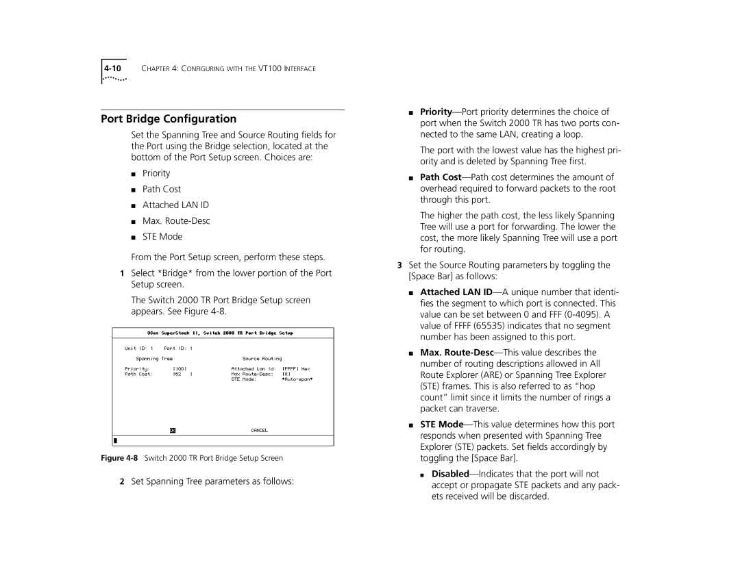
1Select *Bridge* from the lower portion of the Port Setup screen.

The Switch 2000 TR Port Bridge Setup screen appears. See Figure 4-8.

Figure 4-8Switch 2000 TR Port Bridge Setup Screen

2Set Spanning Tree parameters as follows:

Priority—Port priority determines the choice of port when the Switch 2000 TR has two ports con- nected to the same LAN, creating a loop.

The port with the lowest value has the highest pri- ority and is deleted by Spanning Tree first.

Path Cost—Path cost determines the amount of overhead required to forward packets to the root through this port.

The higher the path cost, the less likely Spanning Tree will use a port for forwarding. The lower the cost, the more likely Spanning Tree will use a port for routing.

3Set the Source Routing parameters by toggling the [Space Bar] as follows:

Attached LAN ID—A unique number that identi- fies the segment to which port is connected. This value can be set between 0 and FFF (0-4095). A value of FFFF (65535) indicates that no segment number has been assigned to this port.

Max. Route-Desc—This value describes the number of routing descriptions allowed in All Route Explorer (ARE) or Spanning Tree Explorer (STE) frames. This is also referred to as “hop count” limit since it limits the number of rings a packet can traverse.

STE Mode—This value determines how this port responds when presented with Spanning Tree Explorer (STE) packets. Set fields accordingly by toggling the [Space Bar].

Disabled—Indicates that the port will not accept or propagate STE packets and any pack- ets received will be discarded.

Page 68
Image 68
3Com manual Port Bridge Configuration, 8Switch 2000 TR Port Bridge Setup Screen