Configuring Switch 2000 TR in Stack |
Configuring Switch 2000 TR in Stack
Head Unit
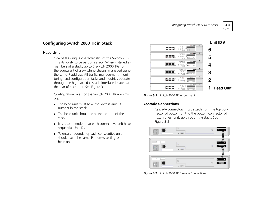
One of the unique characteristics of the Switch 2000 TR is its ability to be part of a stack. When installed as members of a stack, up to 6 Switch 2000 TRs form the equivalent of a switching chassis, managed using the same IP address. All traffic, management, moni- toring, and configuration tasks and inquiries operate through the
|
|
|
| LINK STATUS |
|
| SuperStack II | |||
|
|
|
|
|
|
|
|
|
| Switch 2000 TR |
1x | 6x |
|
|
|
|
|
|
|
|
|
|
| 1 | 2 | 3 | 4 | 5 | 6 |
|
|
|
|
| 1 | 2 | 3 | 4 | 5 | 6 |
|
|
|
7x | 12x | 7 | 8 | 9 | 10 | 11 12 | O | C |
| |
7 | 8 | 9 | 10 | 11 12 | O | C | ENTER | |||
|
|
|
| LINK STATUS |
|
| SuperStack II | |||
|
|
|
|
|
|
|
|
|
| Switch 2000 TR |
1x | 6x |
|
|
|
|
|
|
|
|
|
|
| 1 | 2 | 3 | 4 | 5 | 6 |
|
|
|
|
| 1 | 2 | 3 | 4 | 5 | 6 |
|
|
|
7x | 12x | 7 | 8 | 9 | 10 | 11 12 | O | C |
| |
7 | 8 | 9 | 10 | 11 12 | O | C | ENTER | |||
|
|
|
| LINK STATUS |
|
| SuperStack II | |||
|
|
|
|
|
|
|
|
|
| Switch 2000 TR |
1x | 6x |
|
|
|
|
|
|
|
|
|
|
| 1 | 2 | 3 | 4 | 5 | 6 |
|
|
|
|
| 1 | 2 | 3 | 4 | 5 | 6 |
|
|
|
7x | 12x | 7 | 8 | 9 | 10 | 11 12 | O | C |
| |
7 | 8 | 9 | 10 | 11 12 | O | C | ENTER | |||
|
|
|
| LINK STATUS |
|
| SuperStack II | |||
|
|
|
|
|
|
|
|
|
| Switch 2000 TR |
1x | 6x |
|
|
|
|
|
|
|
|
|
|
| 1 | 2 | 3 | 4 | 5 | 6 |
|
|
|
|
| 1 | 2 | 3 | 4 | 5 | 6 |
|
|
|
7x | 12x | 7 | 8 | 9 | 10 | 11 12 | O | C |
| |
7 | 8 | 9 | 10 | 11 12 | O | C | ENTER | |||
|
|
|
| LINK STATUS |
|
| SuperStack II | |||
|
|
|
|
|
|
|
|
|
| Switch 2000 TR |
1x | 6x |
|
|
|
|
|
|
|
|
|
|
| 1 | 2 | 3 | 4 | 5 | 6 |
|
|
|
|
| 1 | 2 | 3 | 4 | 5 | 6 |
|
|
|
7x | 12x | 7 | 8 | 9 | 10 | 11 12 | O | C |
| |
7 | 8 | 9 | 10 | 11 12 | O | C | ENTER | |||
|
|
|
| LINK STATUS |
|
| SuperStack II | |||
|
|
|
|
|
|
|
|
|
| Switch 2000 TR |
1x | 6x |
|
|
|
|
|
|
|
|
|
|
| 1 | 2 | 3 | 4 | 5 | 6 |
|
|
|
|
| 1 | 2 | 3 | 4 | 5 | 6 |
|
|
|
7x | 12x | 7 | 8 | 9 | 10 | 11 12 | O | C |
| |
7 | 8 | 9 | 10 | 11 12 | O | C | ENTER | |||
Unit ID #
6
5
4
3
2
1 Head Unit
Configuration rules for the Switch 2000 TR are sim- ple:
■The head unit must have the lowest Unit ID number in the stack.
■The head unit should be at the bottom of the stack.
■It is recommended that each consecutive unit have sequential Unit IDs.
■To ensure redundancy each consecutive unit should have the same IP address setting as the head unit.
Figure 3-1 Switch 2000 TR in stack setting.
Cascade Connections
Cascade connectors must attach from the top con- nector of bottom unit to the bottom connector of next highest unit, up through the stack. See Figure