Chapter 2: System Configuration
2.5 Syslog
The Syslog (system log) is a standard for logging program messages. It allows separation of the software that generates messages from the system that stores them and the software that reports and analyzes them. It can also be used for generalized informational, analysis, and debugging messages. It is supported by a wide variety of devices and receivers across multiple platforms.
2.5.1 Configuration
This section describes how to configure the system log and provide a wide variety of devices and receivers across multiple platforms.
Web Interface
To configure syslog configuration in the Web interface:
1.Click SYSTEM, Syslog.
2.Specify the syslog parameters including the IP address of the Syslog server and the port number.
3.Evoke the syslog to enable it.
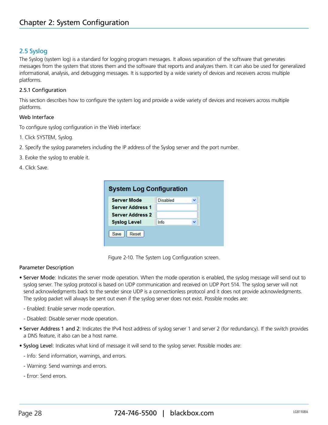
4.Click Save.
Figure 2-10. The System Log Configuration screen.
Parameter Description
•Server Mode: Indicates the server mode operation. When the mode operation is enabled, the syslog message will send out to syslog server. The syslog protocol is based on UDP communication and received on UDP Port 514. The syslog server will not send acknowledgments back to the sender since UDP is a connectionless protocol and it does not provide acknowledgments. The syslog packet will always be sent out even if the syslog server does not exist. Possible modes are:
-Enabled: Enable server mode operation.
-Disabled: Disable server mode operation.
•Server Address 1 and 2: Indicates the IPv4 host address of syslog server 1 and server 2 (for redundancy). If the switch provides a DNS feature, it also can be a host name.
•Syslog Level: Indicates what kind of message it will send to the syslog server. Possible modes are:
-Info: Send information, warnings, and errors.
-Warning: Send warnings and errors.
-Error: Send errors.
Page 28 | LGB1108A | |
|
|