Chapter 3: Configuration
3.8.2 LLDP Neighbors
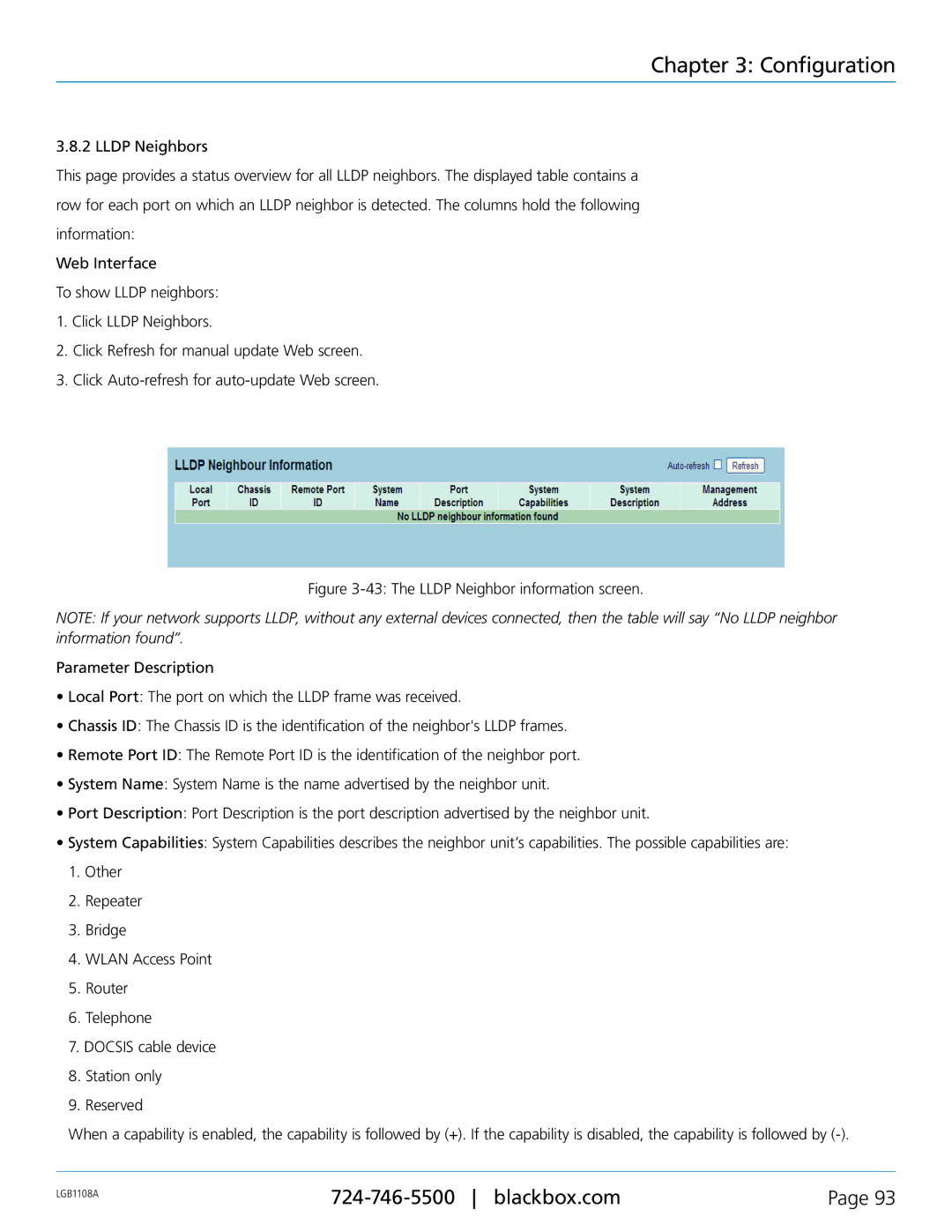
This page provides a status overview for all LLDP neighbors. The displayed table contains a row for each port on which an LLDP neighbor is detected. The columns hold the following information:
Web Interface
To show LLDP neighbors:
1.Click LLDP Neighbors.
2.Click Refresh for manual update Web screen.
3.Click
Figure 3-43: The LLDP Neighbor information screen.
NOTE: If your network supports LLDP, without any external devices connected, then the table will say “No LLDP neighbor information found”.
Parameter Description
•Local Port: The port on which the LLDP frame was received.
•Chassis ID: The Chassis ID is the identification of the neighbor's LLDP frames.
•Remote Port ID: The Remote Port ID is the identification of the neighbor port.
•System Name: System Name is the name advertised by the neighbor unit.
•Port Description: Port Description is the port description advertised by the neighbor unit.
•System Capabilities: System Capabilities describes the neighbor unit’s capabilities. The possible capabilities are:
1.Other
2.Repeater
3.Bridge
4.WLAN Access Point
5.Router
6.Telephone
7.DOCSIS cable device
8.Station only
9.Reserved
When a capability is enabled, the capability is followed by (+). If the capability is disabled, the capability is followed by (-).
LGB1108A | Page 93 | |
|
|