AutoDome 7000 Series IP and HD
Page
Table of contents
Configuration via IP, Advanced Mode
Configuration
Configuration via IP, Basic Mode
VCA
14.32 Alarm Connections 116 14.33
118
Operation 139
Safety Precautions
Safety EN
Important Safety Instructions
About this Manual
AutoDome 7000 Series IP and HD Safety EN en
Coax grounding
Important Notices
AutoDome 7000 Series IP and HD Safety EN en
Informations FCC et Ices
FCC & Ices Information
Service Centers
Customer Support and Service
Connection in Applications
Disclaimer
Technical Support
Customer Service
Repair Center
Canada
Unpacking
Parts List, Installation
Quantity For Mount Type Supplied by Bosch?
Tools Required
AutoDome 7000 Series IP and HDUnpacking en
Only if installing a fiber optic model
Barrel connector Roof parapet Mount Pipe Mount
Necessary to install Autodome cameras
Additional Products Required
System overview
4Pre-installation Checklist
Pole and Mast Mounts
1Stabilization
Roof Mounts
Extreme Mount Applications
Card is optional
Installing the Optional SD Card
Follow these steps
Risk of electrostatic discharge
Bosch Security Systems 2013.07 1.2.2 F.01U.283.679
Corner Mounts
Mount Power Supply Box Wall, Mast Pole,
Bosch Security Systems 2013.07 1.2.2 F.01U.283.679
Route Wires and Attach Connectors
Installing the Pendant Arm Wall, Corner, and Mast
Pole Mounts
Description
Alarm and relay connectors
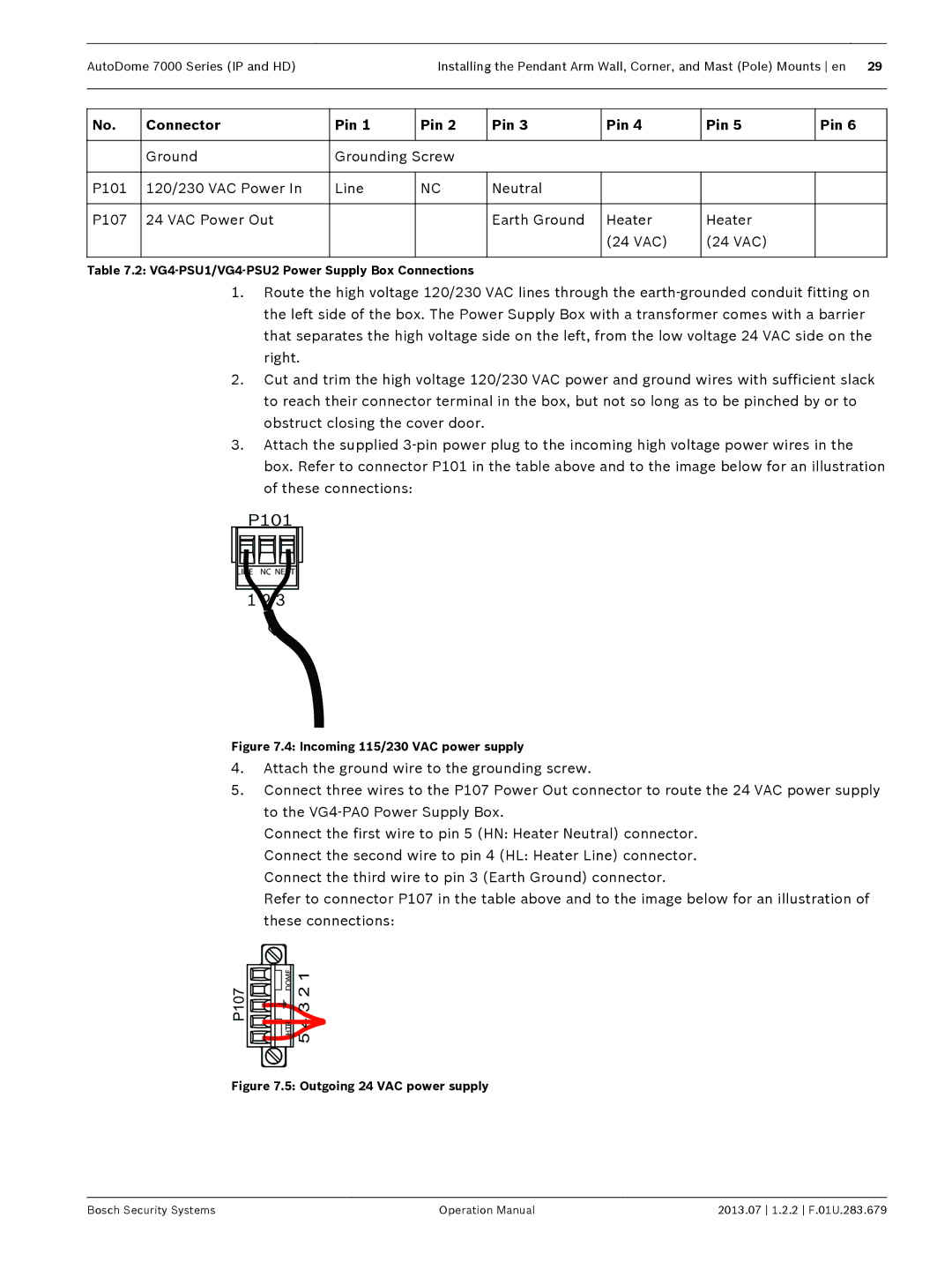
Power Supply Box Connections
VAC
Ground Screw P101 Connector Power In 120 VAC
Serial Code CODE+
Connector Pin
RXD TXD
Communications
VG4-PSU1 / VG4-PSU2
Route Power through Intermediate Power Supply Box
3 2
VG4-PA0 Power Supply Box
Pendant Arm to Power Box Hinge Alignment
Attach Pendant Arm to Power Supply Box
Pendant Arm connections to Power Supply Box
Make Connections in the Power Supply Box
For a Mast or pole installation
6Installing the VGA-PEND-WPLATE
For a Corner installation
Attach the Pendant Arm to the Mounting Plate
Ensure that the mounting plate is secure
10 Pendant Arm Cables
Route and Connect Wires to a Power Supply Box
11 Mounting Plate Inside Detail
Attach Pendant to Arm and Tighten
Rotate down to engage dome connector
Dome Connector
Tilt up
Hook and drop
Bosch Security Systems 2013.07 1.2.2 F.01U.283.679
VGA-ROOF-MOUNT
Installing the Roof Parapet and Pipe Mounts
VG4-A-PSU1 or VG4-A-PSU2 Power Supply Box
Pipe Interface Board
Wiring the Power Supply Box
VG4-A-PSU1/VG4-A-PSU2
Wiring the Fiber Optic Model
Fiber Optic Ethernet Module installed
Contro L IN/OUT
Align Cover Door Hinge to Power Box
Attach Cover Door to Power Supply Box
VGA-ROOF-MOUNT
Installing the VGA-ROOF-MOUNT
VGA-ROOF-MOUNT
Bolt and attach both ends to anchor spots on the roof
Installing the VG4-A-9543 Pipe Mount
10 Pipe Mount
6Wire the Pipe Interface Board
P105 J102 P102 P104
BNC
P107 J101 P106
Pipe Interface Module Video Coax J102
OUT +
AWG
COM
Pin Description Alarm Out Normally Open
Attach Pendant to Pipe and Tighten
Connectors for any blocked pin holes and bent pins
Interface Board Retaining Screws Pendant Mounting Screws
Recessed hinge pin of the Dome Cap
14 Pendant to Roof / Pipe Mount Attachment
Tilt Dome
Right side of the box
Connector P101 on the left side of the box
Dimensions
Installing the In-Ceiling Mount
Prepare Drywall Ceiling for Installation
Prepare Suspension Ceiling for Installation
Suspension Ceiling Bracket Top View
Tighten the four 4 securing screws to the Bracket Assembly
Hole which will not be used to route wires
Wire the Interface Box
Interface Box Connections
Interface Box Connections
Communi
Agnd
GND Cations
OUT
Instructions
Installing the Ceiling IP54 Housing Gasket
In-ceiling IP54 Rating Installation Diagram
Attach Housing to the Interface Box
10 Attach Housing to Interface Box
12 Secure camera to ceiling
Secure Housing to Ceiling
Remove the bubble from a pendant housing
Remove the bubble from an in-ceiling housing
Preparing the Bubble
Remove the foam inserts surrounding the camera module
Pendant Bubble Release Opening
Replace the trim ring optional In-ceiling models
Replace the bubble in a pendant housing
Replace the bubble in an in-ceiling housing
11.2 Power Cable and Wire Distances Guides
11.1 Connecting the Autodome camera to the PC
Power 115/230 VAC Copper Wire To comply with local codes
Connection
11.3 Ethernet Connections
11.4 Fiber Optic Ethernet Media Converter Optional
11.5 Alarms and Relay Connections
Contact Alarm Condition Open Closed Normal Short Tamper
Configuring a Normally Closed Supervised Alarm
AutoDome Programmed N.O.S
AutoDome Programmed N.C.S
Configuring a Normally Open Non-supervised Alarm
Configuring Non-supervised Alarms inputs 3 through
Configuring a Normally Closed Non-supervised Alarm
AutoDome Programmed N.O
11.6 Audio Connections Optional
Audio Line Level Output Connections
Wire Specifications
Audio Line Level Input Connections
12.1 System Requirements
Configuration
Using the Autodome 7000 Series Web Server
12.2 Configuring the Autodome 7000 Series Camera
Using the Configuration Manager
Network Access
Basic Mode menu
About the Settings
Making Changes
Starting Configuration
Navigation
Pre-programmed User Modes
12.3 Configuring Audio Optional
Enabling Audio Transmission
Activating Audio Reception
13.1 Basic Mode Device Access
Configuration via IP, Basic Mode
Password
Confirm password
13.3 Basic Mode Network
13.2 Basic Mode Date/Time
13.4 Basic Mode Encoder
13.7 Basic Mode System Overview
13.5 Basic Mode Audio
13.6 Basic Mode Recording
14.1 Advanced Mode General Identification
Configuration via IP, Advanced Mode
See also
Camera ID
Date/Time
Password
Date format
Device date/Device time
Daylight saving time
14.5 Display Stamping
Camera name stamping
Time stamping
14.6 Advanced Mode Web Interface
Appearance
14.8 Livepage Functions
Logging
Advanced Mode Camera Installer Menu
Reboot device
SC settings
Factory defaults
Max Frame Rate Option Available Streaming Options
Advanced ModeCameraEncoder Profile
Encoder Profile
DSL
Expert Settings
Video resolution
Profile name
Target bit rate
Encoder Streams
MP SD SD stream options
Default profile
Property
Autodome IP Profiles Autodome HD Profiles
Jpeg stream
Privacy Masks
Preview
Camera Settings
Night mode
Shutter Mode
Fixed Gain
Maximum Gain Level
Lens Settings
PTZ Settings
Prepositions and Tours
Diagnostics
Compass
To define and edit an individual scene
Logs
Sectors
Miscellaneous
Input volume
Advanced Mode Recording
Audio
Pixel Counter
Storage Management
Device manager
Activating and Configuring Storage Media
Recording media
ISCSI Media
Deactivating Storage Media
Recording Profiles
Formatting Storage Media
Standard recording
Maximum Retention Time
Recording Scheduler
Recording Status
Connect on alarm
Advanced Mode Alarm Alarm Connections
Destination password
Number of destination IP address
Stream
Video transmission
Remote port
Video output
14.33 VCA
Select On to activate audio alarms
Auto-connect
VCA Profiles
Select Off or Test
VCA configuration
Preset
Aggregation times
Alarm status
Analysis type
Motion detector MOTION+ only
Select Area MOTION+ only
Debounce time 1 s MOTION+ only
2013.07 1.2.2 F.01U.283.679 Bosch Security Systems
Tamper detection
Trigger delay s
Sensitivity
Global change
Reference Check
Virtual Masks
Disappearing edges
Appearing edges
Audio alarm
Audio Alarm
Select On if you want the device to generate audio alarms
Name
Alarm E-Mail
Alarm Rules
Alarm Task Editor
Advanced Mode Network Network Access
Advanced Mode Interfaces Alarm Inputs
Alarm Outputs
IPv4
Automatic IP assignment
Fill in the 3 fields in this section of the screen
IPv6
DNS server address 1 / DNS server address
Prefix length
Details
TCP rate control
Http browser port
Interface mode ETH
Https browser port
RCP+ port
DynDNS
Enable DynDNS
Provider
Host name
Advanced
User Mode
Quality of service
Multicast
TCP port
Image Posting
Encryption
Accounts
14.48 IPv4 Filter
Advanced Mode Service Maintenance
Maintenance log
192.168.0.10/reset
Licenses
System Overview
Settings, and to configure the network parameters
15.1 Using the Autodome Camera
Operation
Display Stamping
Protected AutoDome
Maximum Number of Connections
Protected Network
Image Selection
Digital I/O
Preset List
Triggering Relay
System Log
Aux Control Tab
Audio function
To View a Preset Shot
To Enter a Keyboard Control Command
To Set a Preset Shot
Scan
Livepage Special Functions
Autopan
Findhome
Selecting Recordings
Image Resolution
Processor Load
Bookmarks
Export to FTP
Controlling Playback
Configuring Intelligent Tracking
15.2 Using Intelligent Tracking
Guidelines for Implementing Intelligent Tracking
Mount/Mounting Surface Stability
Field of View
Using Intelligent Tracking
Unwanted Motion
Operation of Intelligent Tracking
Continuous Guard Tours
Guard Tours and Preset Tours
Recommended Use of Your Camera
Scene Illumination and Focus Settings
Preset Tours
Power-over-Ethernet PoE
Installation in an area with high humidity
Upgrading the AutoDome 800 Series
Outdoor installation
SD card
Beginning the Firmware Update Process
Problem Questions to Ask/Actions to Resolve the Problem
Troubleshooting
If O.K., then
If camera’s IP address is not set, then
Expand the Service Settings link, then click Network
Access the Settings Web page for the IP-enabled device
ON/OFF
Contact Bosch Technical Support
Bubble Cleaning
Maintenance
Cleaning the Bubble Interior
Bubble Handling
Remove an SD card
Cleaning the Bubble Exterior
Technical data
Some of the following commands may not apply to your camera
User Command Table
AutoDome 7000 Series IP and HDUser Command Table en
Index
AutoDome 7000 Series IP and HD Index en
En Index AutoDome 7000 Series IP and HD
AutoDome 7000 Series IP and HD Index en
Udpip UDP
Page
Bosch Security Systems, Inc