Chapter 1 Cisco uBR10012 Universal Broadband Router Overview
Cisco uBR10012 Universal Broadband Router Modules
When two TCC+ cards are installed, they are configured as active and backup (redundant). If the TCC+ card in the first slot is working at system
Each TCC+ card contains two
Caution The TCC+ card can connect only to a national clock source such as a GPS receiver or BITS clock. The Cisco uBR10012 router does not support connecting the
If present, the primary external clock reference on the active TCC+ card is used. If it is lost, the secondary clock reference on the active TCC+ card is used. If the active TCC+ card stops functioning, control is transferred to the backup TCC+ card, which then uses its primary and secondary clock reference sources. If neither card has a valid clock reference source, the active TCC+ card uses its own internal clock to provide the
Note You do not need to provide any external clock reference source to the TCC+ cards. However, you must always have at least one functioning TCC+ card installed in the Cisco uBR10012 chassis to ensure proper systems operation.
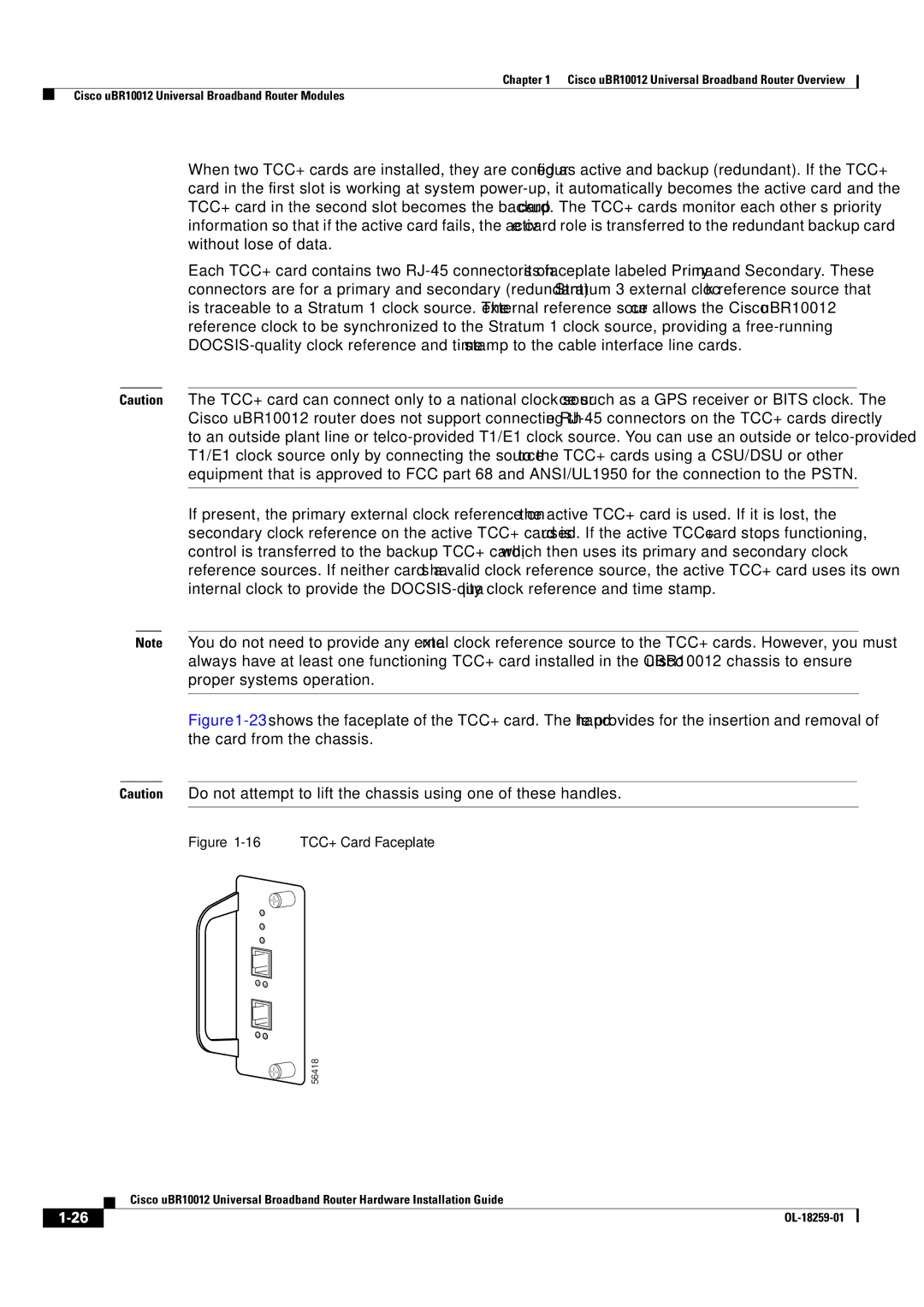
Figure 1-23 shows the faceplate of the TCC+ card. The handle provides for the insertion and removal of the card from the chassis.
Caution Do not attempt to lift the chassis using one of these handles.
Figure 1-16 TCC+ Card Faceplate
56418
| Cisco uBR10012 Universal Broadband Router Hardware Installation Guide |