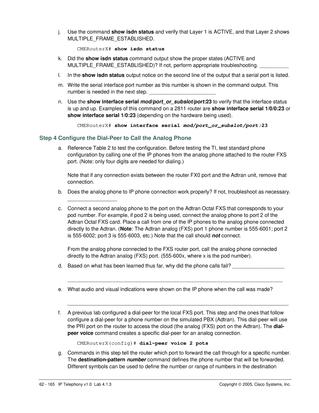
j.Use the command show isdn status and verify that Layer 1 is ACTIVE, and that Layer 2 shows
MULTIPLE_FRAME_ESTABLISHED.
CMERouterX# show isdn status
k.Did the show isdn status command output show the proper states (ACTIVE and
MULTIPLE_FRAME_ESTABLISHED)? If not, perform appropriate troubleshooting. __________
l.In the show isdn status output notice on the second line of the output that a serial port is listed.
m.Write the serial interface port number as this number is shown in the command output. This number is needed in the next step. _______________________
n.Use the show interface serial mod/port_or_subslot/port:23 to verify that the interface status is up and up. Examples of this command on a 2811 router are show interface serial 1/0/0:23 or show interface serial 1/0:23 (depending on the hardware being used).
CMERouterX# show interface serial mod/port_or_subslot/port:23
Step 4 Configure the Dial-Peer to Call the Analog Phone
a.Reference Table 2 to test the configuration. Before testing the TI, test standard phone configuration by calling one of the IP phones from the analog phone attached to the router FXS port. (Note: only four digits are needed for dialing.)
Note that if any connection exists between the router FX0 port and the Adtran unit, remove that connection.
b.Does the analog phone to IP phone connection work properly? If not, troubleshoot as necessary.
_________________
c.Connect a second analog phone to the port on the Adtran Octal FXS that corresponds to your pod number. For example, if pod 2 is being used, connect the analog phone to port 2 of the Adtran Octal FXS card. Place a call from one of the IP phones to the analog phone connected directly to the Adtran. (Note: The Adtran analog (FXS) port 1 phone number is
From the analog phone connected to the FXS router port, call the analog phone connected directly to the Adtran analog (FXS) port.
d.Based on what has been learned thus far, why did the phone calls fail? __________________
__________________________________________________________________________
e.What audio and visual indications were shown on the IP phone when the call was made?
____________________________________________________________________________
f.A previous lab configured a
CMERouterX(config)# dial-peer voice 2 pots
g.Commands in this step tell the router which port to forward the call through for a specific number. The
62 - 165 IP Telephony v1.0 Lab 4.1.3 | Copyright ♥ 2005, Cisco Systems, Inc. |
