MODEL 3081 pH/ORP | SECTION 12.0 |
| TROUBLESHOOTING |
C.Check the transmitter.
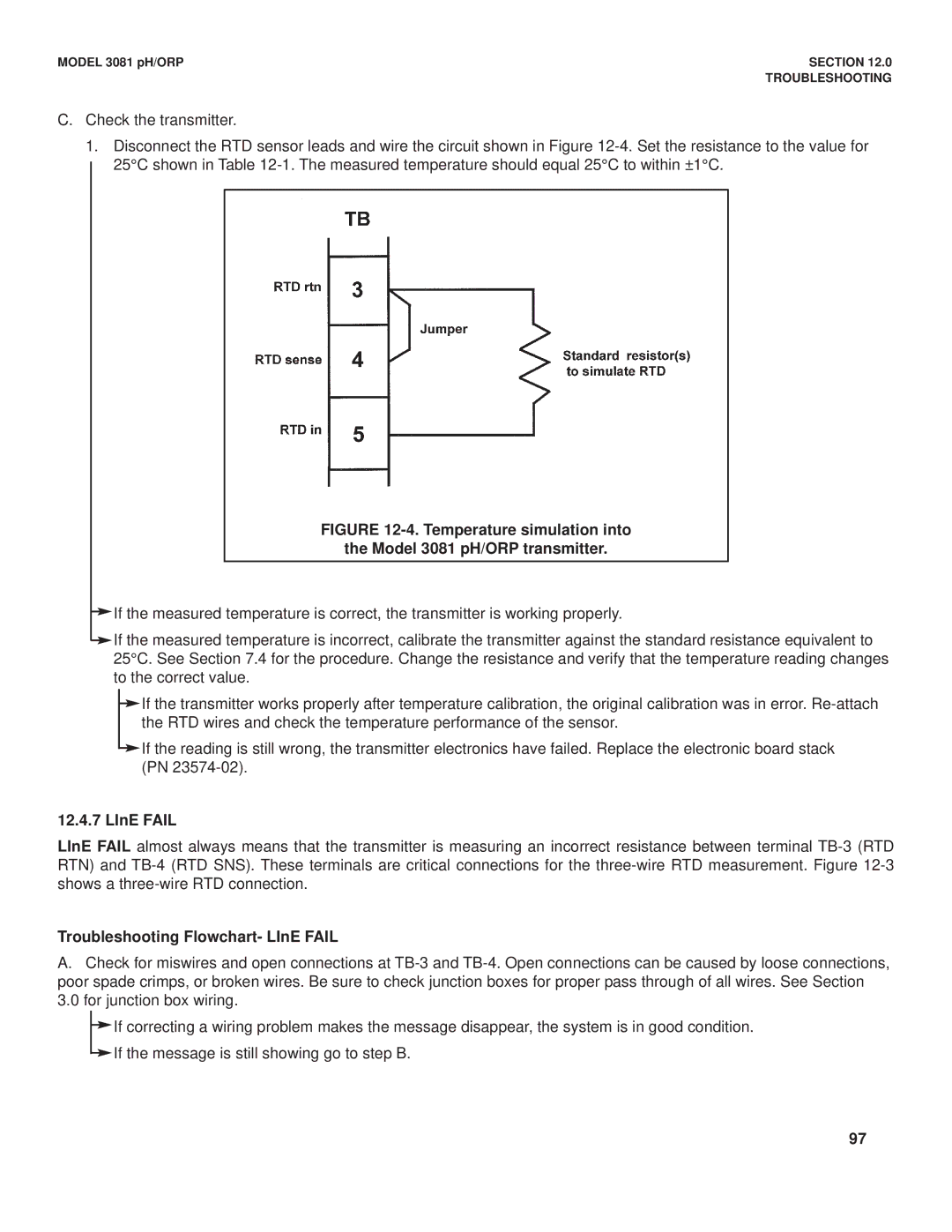
1.Disconnect the RTD sensor leads and wire the circuit shown in Figure
FIGURE 12-4. Temperature simulation into
the Model 3081 pH/ORP transmitter.
If the measured temperature is correct, the transmitter is working properly.
If the measured temperature is incorrect, calibrate the transmitter against the standard resistance equivalent to 25°C. See Section 7.4 for the procedure. Change the resistance and verify that the temperature reading changes to the correct value.
If the transmitter works properly after temperature calibration, the original calibration was in error.
If the reading is still wrong, the transmitter electronics have failed. Replace the electronic board stack (PN
12.4.7 LInE FAIL
LInE FAIL almost always means that the transmitter is measuring an incorrect resistance between terminal
Troubleshooting Flowchart- LInE FAIL
A.Check for miswires and open connections at
If correcting a wiring problem makes the message disappear, the system is in good condition. If the message is still showing go to step B.
97