MODEL 3081 pH/ORP | SECTION 2.0 |
| INSTALLATION |
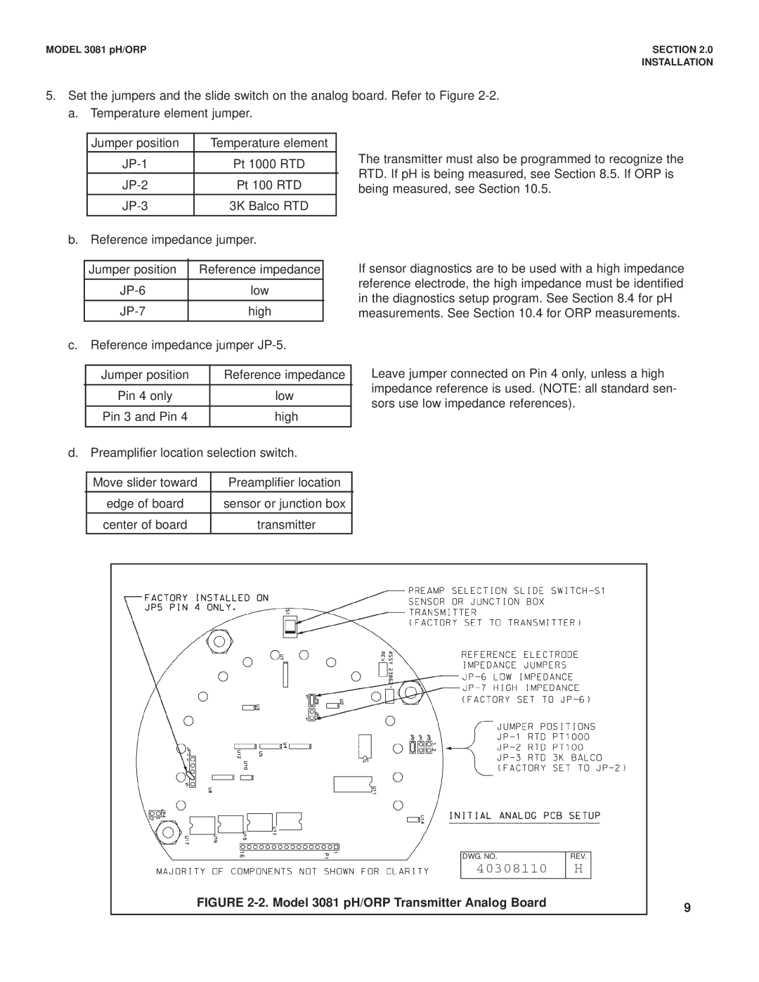
5. Set the jumpers and the slide switch on the analog board. Refer to Figure
a. | Temperature element jumper. |
| |
|
|
|
|
| Jumper position | Temperature element |
|
| Pt 1000 RTD |
| |
| Pt 100 RTD |
| |
| 3K Balco RTD |
| |
b. | Reference impedance jumper. |
| |
The transmitter must also be programmed to recognize the RTD. If pH is being measured, see Section 8.5. If ORP is being measured, see Section 10.5.
Jumper position | Reference impedance |
low | |
high |
c.Reference impedance jumper
If sensor diagnostics are to be used with a high impedance reference electrode, the high impedance must be identified in the diagnostics setup program. See Section 8.4 for pH measurements. See Section 10.4 for ORP measurements.
| Jumper position | Reference impedance |
| Pin 4 only | low |
|
|
|
| Pin 3 and Pin 4 | high |
Leave jumper connected on Pin 4 only, unless a high impedance reference is used. (NOTE: all standard sen- sors use low impedance references).
d. Preamplifier location selection switch.
| Move slider toward | Preamplifier location |
| edge of board | sensor or junction box |
| center of board | transmitter |
DWG. NO. | REV. |
40308110 | H |
FIGURE 2-2. Model 3081 pH/ORP Transmitter Analog Board
9
