MODEL 3081 pH/ORP |
|
|
|
|
|
|
|
| SECTION 3.0 | |||||
|
|
|
|
|
|
|
|
|
|
|
| WIRING | ||
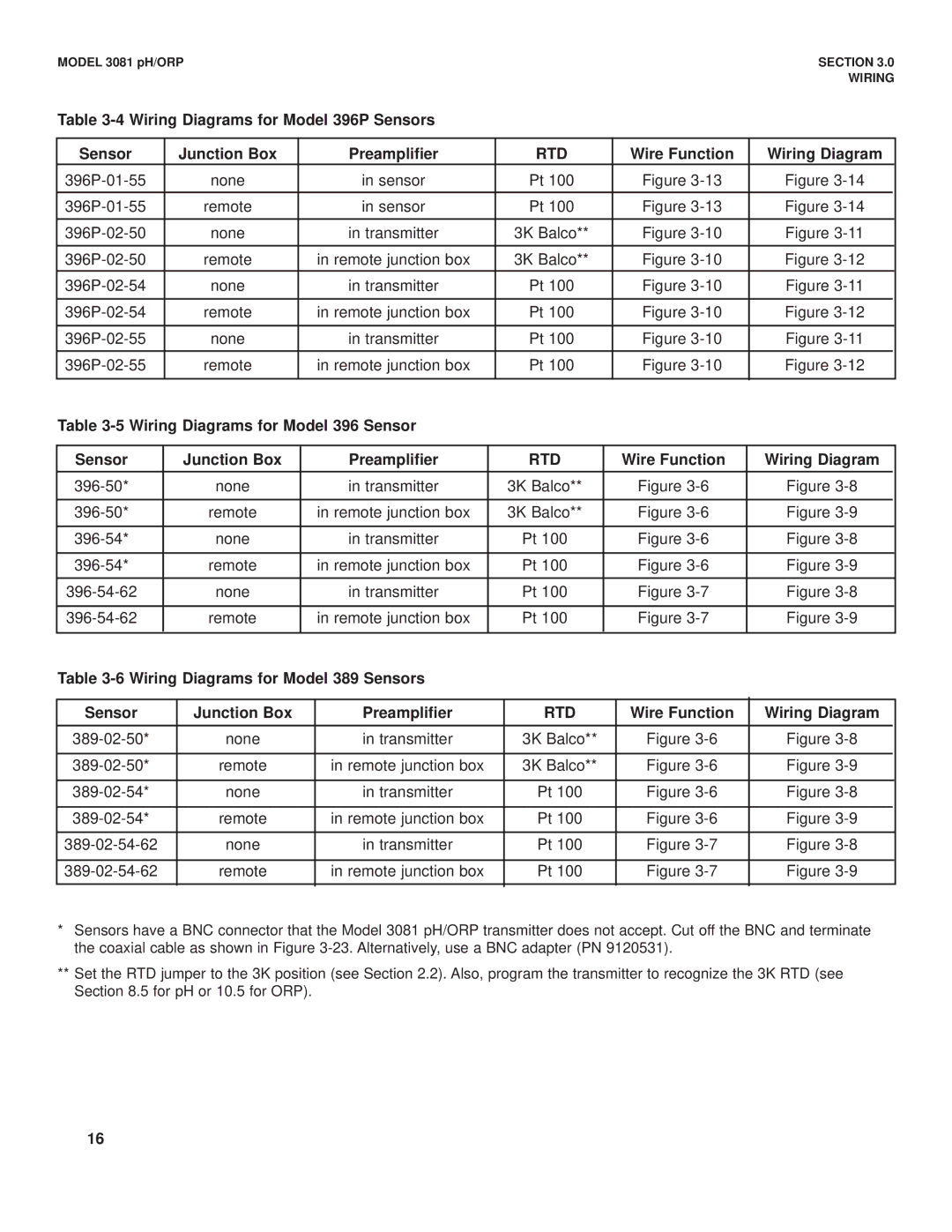
Table |
|
|
|
|
|
|
|
|
| |||||
|
|
|
|
|
|
|
|
|
|
|
|
| ||
Sensor |
| Junction Box |
|
| Preamplifier |
|
| RTD |
|
| Wire Function | Wiring Diagram |
| |
| none |
|
| in sensor |
|
| Pt 100 |
|
| Figure | Figure |
| ||
| remote |
|
| in sensor |
|
| Pt 100 |
|
| Figure | Figure |
| ||
| none |
|
| in transmitter |
|
| 3K Balco** |
|
| Figure | Figure | |||
|
|
|
|
|
|
|
|
|
|
|
|
|
| |
| remote |
|
| in remote junction box |
|
| 3K Balco** |
|
| Figure | Figure |
| ||
| none |
|
| in transmitter |
|
| Pt 100 |
|
| Figure | Figure | |||
|
|
|
|
|
|
|
|
|
|
|
|
|
| |
| remote |
|
| in remote junction box |
|
| Pt 100 |
|
| Figure | Figure | |||
|
|
|
|
|
|
|
|
|
|
|
|
|
| |
| none |
|
| in transmitter |
|
| Pt 100 |
|
| Figure | Figure |
| ||
| remote |
|
| in remote junction box |
|
| Pt 100 |
|
| Figure | Figure | |||
|
|
|
|
|
|
|
|
|
|
|
| |||
Table |
|
|
|
|
|
|
|
|
| |||||
|
|
|
|
|
|
|
|
|
|
|
|
|
|
|
Sensor |
| Junction Box |
| Preamplifier |
|
| RTD |
|
| Wire Function | Wiring Diagram |
| ||
| none |
| in transmitter |
|
| 3K Balco** |
|
| Figure | Figure | ||||
|
|
|
|
|
|
|
|
|
|
|
|
|
|
|
| remote |
| in remote junction box |
|
| 3K Balco** |
|
| Figure | Figure | ||||
|
|
|
|
|
|
|
|
|
|
|
|
|
| |
| none |
| in transmitter |
|
| Pt 100 |
|
| Figure | Figure | ||||
|
|
|
|
|
|
|
|
|
|
|
|
|
| |
| remote |
| in remote junction box |
|
| Pt 100 |
|
| Figure | Figure | ||||
|
|
|
|
|
|
|
|
|
|
|
|
| ||
| none |
| in transmitter |
|
| Pt 100 |
|
| Figure | Figure | ||||
|
|
|
|
|
|
|
|
|
|
|
|
|
| |
| remote |
| in remote junction box |
|
| Pt 100 |
|
| Figure | Figure | ||||
|
|
|
|
|
|
|
|
|
|
|
|
|
|
|
Table |
|
|
|
|
|
|
|
|
| |||||
|
|
|
|
|
|
|
|
|
|
|
|
| ||
Sensor |
| Junction Box |
| Preamplifier |
|
| RTD |
|
| Wire Function | Wiring Diagram |
| ||
| none |
| in transmitter |
|
| 3K Balco** |
|
| Figure | Figure | ||||
|
|
|
|
|
|
|
|
|
|
|
|
|
| |
| remote |
| in remote junction box |
|
| 3K Balco** |
|
| Figure | Figure | ||||
|
|
|
|
|
|
|
|
|
|
|
|
|
| |
| none |
| in transmitter |
|
| Pt 100 |
|
| Figure | Figure | ||||
|
|
|
|
|
|
|
|
|
|
|
|
| ||
| remote |
| in remote junction box |
|
| Pt 100 |
|
| Figure | Figure |
| |||
|
|
|
|
|
|
|
|
|
|
|
|
| ||
| none |
| in transmitter |
|
| Pt 100 |
|
| Figure | Figure | ||||
|
|
|
|
|
|
|
|
|
|
|
|
| ||
| remote |
| in remote junction box |
|
| Pt 100 |
|
| Figure | Figure |
| |||
*Sensors have a BNC connector that the Model 3081 pH/ORP transmitter does not accept. Cut off the BNC and terminate the coaxial cable as shown in Figure
**Set the RTD jumper to the 3K position (see Section 2.2). Also, program the transmitter to recognize the 3K RTD (see Section 8.5 for pH or 10.5 for ORP).
16