MODEL 3081 pH/ORP | SECTION 2.0 |
| INSTALLATION |
2.5 POWER SUPPLY/CURRENT LOOP
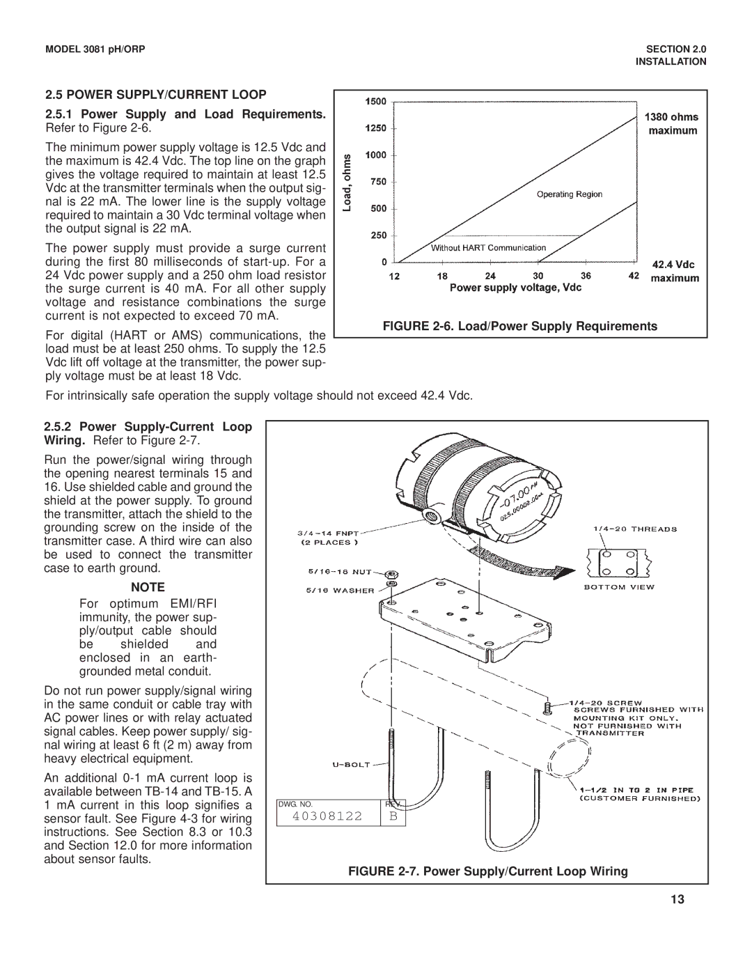
2.5.1Power Supply and Load Requirements. Refer to Figure 2-6.
The minimum power supply voltage is 12.5 Vdc and the maximum is 42.4 Vdc. The top line on the graph gives the voltage required to maintain at least 12.5 Vdc at the transmitter terminals when the output sig- nal is 22 mA. The lower line is the supply voltage required to maintain a 30 Vdc terminal voltage when the output signal is 22 mA.
The power supply must provide a surge current during the first 80 milliseconds of
For digital (HART or AMS) communications, the load must be at least 250 ohms. To supply the 12.5 Vdc lift off voltage at the transmitter, the power sup- ply voltage must be at least 18 Vdc.
FIGURE 2-6. Load/Power Supply Requirements
For intrinsically safe operation the supply voltage should not exceed 42.4 Vdc.
2.5.2Power Supply-Current Loop Wiring. Refer to Figure 2-7.
Run the power/signal wiring through the opening nearest terminals 15 and
16.Use shielded cable and ground the shield at the power supply. To ground the transmitter, attach the shield to the grounding screw on the inside of the transmitter case. A third wire can also be used to connect the transmitter case to earth ground.
NOTE
For optimum EMI/RFI immunity, the power sup- ply/output cable should
be shielded and enclosed in an earth- grounded metal conduit.
Do not run power supply/signal wiring in the same conduit or cable tray with AC power lines or with relay actuated signal cables. Keep power supply/ sig- nal wiring at least 6 ft (2 m) away from heavy electrical equipment.
An additional
DWG. NO. | REV. |
40308122 | B |
|
|
FIGURE 2-7. Power Supply/Current Loop Wiring
13