MODEL 3081 pH/ORP | SECTION 12.0 |
| TROUBLESHOOTING |
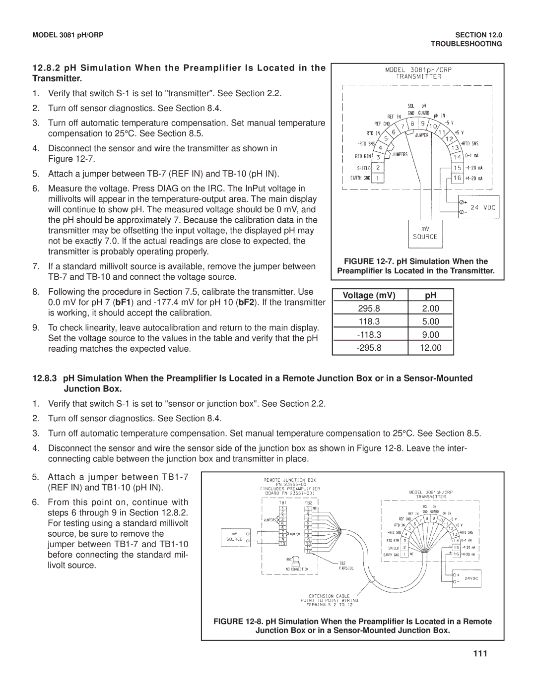
12.8.2pH Simulation When the Preamplifier Is Located in the Transmitter.
1.Verify that switch
2.Turn off sensor diagnostics. See Section 8.4.
3.Turn off automatic temperature compensation. Set manual temperature compensation to 25°C. See Section 8.5.
4.Disconnect the sensor and wire the transmitter as shown in Figure
5.Attach a jumper between
6.Measure the voltage. Press DIAG on the IRC. The InPut voltage in millivolts will appear in the
7.If a standard millivolt source is available, remove the jumper between
8.Following the procedure in Section 7.5, calibrate the transmitter. Use 0.0 mV for pH 7 (bF1) and
9.To check linearity, leave autocalibration and return to the main display. Set the voltage source to the values in the table and verify that the pH reading matches the expected value.
FIGURE 12-7. pH Simulation When the Preamplifier Is Located in the Transmitter.
| Voltage (mV) | pH |
|
| 295.8 | 2.00 |
|
| 118.3 | 5.00 |
|
| 9.00 |
| |
| 12.00 |
|
12.8.3pH Simulation When the Preamplifier Is Located in a Remote Junction Box or in a
1.Verify that switch
2.Turn off sensor diagnostics. See Section 8.4.
3.Turn off automatic temperature compensation. Set manual temperature compensation to 25°C. See Section 8.5.
4.Disconnect the sensor and wire the sensor side of the junction box as shown in Figure
5.Attach a jumper between
6.From this point on, continue with steps 6 through 9 in Section 12.8.2. For testing using a standard millivolt source, be sure to remove the jumper between