MODEL 3081 pH/ORP | TABLE OF CONTENTS |
TABLE OF CONTENTS - CONT’D
LIST OF FIGURES - CONT’D
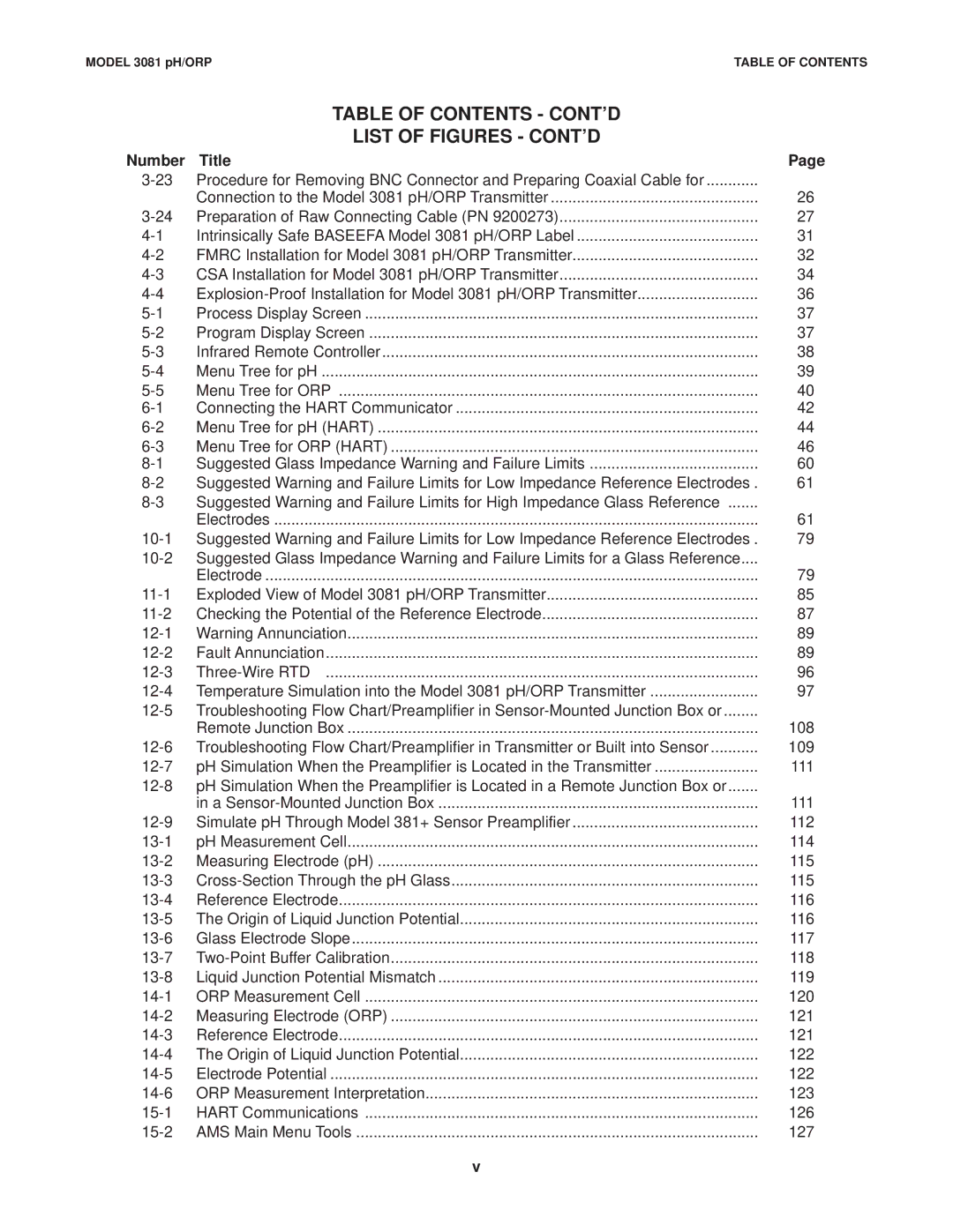
Number | Title | Page |
Procedure for Removing BNC Connector and Preparing Coaxial Cable for |
| |
| Connection to the Model 3081 pH/ORP Transmitter | 26 |
Preparation of Raw Connecting Cable (PN 9200273) | 27 | |
Intrinsically Safe BASEEFA Model 3081 pH/ORP Label | 31 | |
FMRC Installation for Model 3081 pH/ORP Transmitter | 32 | |
CSA Installation for Model 3081 pH/ORP Transmitter | 34 | |
36 | ||
Process Display Screen | 37 | |
Program Display Screen | 37 | |
Infrared Remote Controller | 38 | |
Menu Tree for pH | 39 | |
Menu Tree for ORP | 40 | |
Connecting the HART Communicator | 42 | |
Menu Tree for pH (HART) | 44 | |
Menu Tree for ORP (HART) | 46 | |
Suggested Glass Impedance Warning and Failure Limits | 60 | |
Suggested Warning and Failure Limits for Low Impedance Reference Electrodes . | 61 | |
Suggested Warning and Failure Limits for High Impedance Glass Reference |
| |
| Electrodes | 61 |
Suggested Warning and Failure Limits for Low Impedance Reference Electrodes . | 79 | |
Suggested Glass Impedance Warning and Failure Limits for a Glass Reference.... |
| |
| Electrode | 79 |
Exploded View of Model 3081 pH/ORP Transmitter | 85 | |
Checking the Potential of the Reference Electrode | 87 | |
Warning Annunciation | 89 | |
Fault Annunciation | 89 | |
96 | ||
Temperature Simulation into the Model 3081 pH/ORP Transmitter | 97 | |
Troubleshooting Flow Chart/Preamplifier in |
| |
| Remote Junction Box | 108 |
Troubleshooting Flow Chart/Preamplifier in Transmitter or Built into Sensor | 109 | |
pH Simulation When the Preamplifier is Located in the Transmitter | 111 | |
pH Simulation When the Preamplifier is Located in a Remote Junction Box or |
| |
| in a | 111 |
Simulate pH Through Model 381+ Sensor Preamplifier | 112 | |
pH Measurement Cell | 114 | |
Measuring Electrode (pH) | 115 | |
115 | ||
Reference Electrode | 116 | |
The Origin of Liquid Junction Potential | 116 | |
Glass Electrode Slope | 117 | |
118 | ||
Liquid Junction Potential Mismatch | 119 | |
ORP Measurement Cell | 120 | |
Measuring Electrode (ORP) | 121 | |
Reference Electrode | 121 | |
The Origin of Liquid Junction Potential | 122 | |
Electrode Potential | 122 | |
ORP Measurement Interpretation | 123 | |
HART Communications | 126 | |
AMS Main Menu Tools | 127 |
v
