MODEL 3081 pH/ORP | SECTION 13.0 |
| pH MEASUREMENTS |
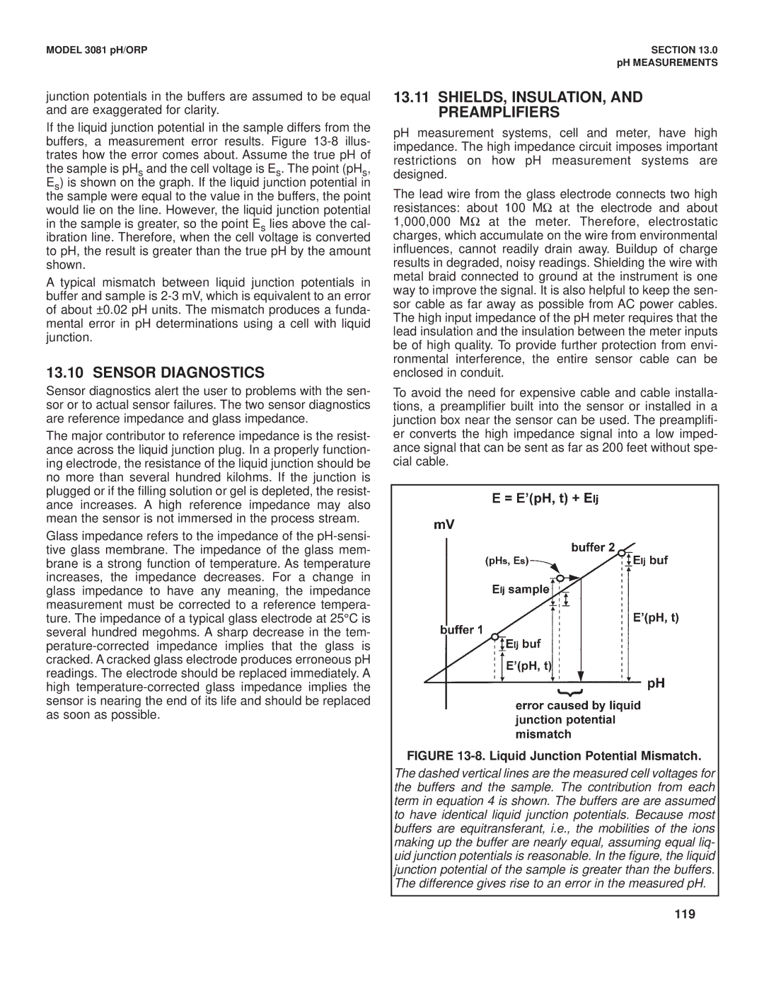
junction potentials in the buffers are assumed to be equal and are exaggerated for clarity.
If the liquid junction potential in the sample differs from the buffers, a measurement error results. Figure
A typical mismatch between liquid junction potentials in buffer and sample is
13.10 SENSOR DIAGNOSTICS
Sensor diagnostics alert the user to problems with the sen- sor or to actual sensor failures. The two sensor diagnostics are reference impedance and glass impedance.
The major contributor to reference impedance is the resist- ance across the liquid junction plug. In a properly function- ing electrode, the resistance of the liquid junction should be no more than several hundred kilohms. If the junction is plugged or if the filling solution or gel is depleted, the resist- ance increases. A high reference impedance may also mean the sensor is not immersed in the process stream.
Glass impedance refers to the impedance of the
13.11SHIELDS, INSULATION, AND PREAMPLIFIERS
pH measurement systems, cell and meter, have high impedance. The high impedance circuit imposes important restrictions on how pH measurement systems are designed.
The lead wire from the glass electrode connects two high resistances: about 100 MΩ at the electrode and about 1,000,000 MΩ at the meter. Therefore, electrostatic charges, which accumulate on the wire from environmental influences, cannot readily drain away. Buildup of charge results in degraded, noisy readings. Shielding the wire with metal braid connected to ground at the instrument is one way to improve the signal. It is also helpful to keep the sen- sor cable as far away as possible from AC power cables. The high input impedance of the pH meter requires that the lead insulation and the insulation between the meter inputs be of high quality. To provide further protection from envi- ronmental interference, the entire sensor cable can be enclosed in conduit.
To avoid the need for expensive cable and cable installa- tions, a preamplifier built into the sensor or installed in a junction box near the sensor can be used. The preamplifi- er converts the high impedance signal into a low imped- ance signal that can be sent as far as 200 feet without spe- cial cable.
FIGURE 13-8. Liquid Junction Potential Mismatch.
The dashed vertical lines are the measured cell voltages for the buffers and the sample. The contribution from each term in equation 4 is shown. The buffers are are assumed to have identical liquid junction potentials. Because most buffers are equitransferant, i.e., the mobilities of the ions making up the buffer are nearly equal, assuming equal liq- uid junction potentials is reasonable. In the figure, the liquid junction potential of the sample is greater than the buffers. The difference gives rise to an error in the measured pH.
