HP LaserJet 5000, 5000 N 5000 GN Printers
HP LaserJet 5000, 5000 N, and 5000 GN Printers
Copyright Hewlett-Packard Company
Contents
Printer Operation
Functional Information
Removing and Replacing Parts
Index
Contents
Overview
Printer Description
Printer Features
Printer Features
2Printer Description
Paper Path
4Printer Description
Model and Serial Numbers
Identification
6Printer Description
Site Requirements
Space Requirements
2Printer Dimensions, HP LaserJet
8Printer Description
3Printer Dimensions, HP LaserJet 5000 N/5000 GN
4Printer Dimensions, HP LaserJet 5000 with Accessories
Printer Weight without toner cartridge
Environmental Requirements
Acoustic Emissions Per ISO Printer State Sound Power
10Printer Description
Paper Specifications
12Printer Description
By 8.2
14Printer Description
Supported Types of Paper
Guidelines for Using Paper
16Printer Description
11. Paper Weight Equivalence
Paper Weight Equivalence Table
Label Construction
Labels
Transparencies
Vellum
Envelope Construction
Envelopes
Envelopes with Double-Side-Seams
Envelope Storage
Card Stock and Heavy Paper
Envelopes with Adhesive Strips or Flaps
Envelope Margins
Card Stock Guidelines
Card Stock Construction
22Printer Description
Safety Information
Laser Safety Statement
Canadian DOC Regulations
FCC Regulations
Varning
Laser statement for Finland Luokan 1 laserlaite
Klass 1 Laser Apparat
Varoitus
Material Safety Data Sheet
Printer design eliminates
Environmental Product Stewardship
Protecting the Environment
This HP LaserJet printer design reduces
Service Approach
2Service Approach
Service Approach
Ordering Information
Parts and Supplies
Helpful Documentation
4Service Approach
Helpful Documentation Description or Use Part Number
Technical Assistance
Phone Numbers for Ordering
Exchange Program
Consumables
HP CompuServe Forum
6Service Approach
HP FIRST, Europe
Other Areas
North American Response Center Narc
Recycling Toner Cartridges
8Service Approach
Toner Cartridge Information
Refilled Toner Cartridges
Warranty Statement
10Service Approach
Printer Operation
Control Panel Lights LightIndication
Using the Control Panel
Control Panel Layout
Control Panel Lights
Control Panel Keys Function
Control Panel Keys
Paper Size
Setting or Default Explanation
Settings and Defaults
Setting the Display Language
Settings and Defaults
Control Panel Menus
To change a Control Panel setting
To print a Control Panel menu map
6Printer Operation
Print Menu MAP Print Configuration
Information Menu
Information Menu ItemExplanation
Tray 1 TYPE= Plain Tray 2 TYPE= Tray 3 TYPE=
Paper Handling Menu
Paper Handling Menu ValuesExplanation
Tray 1 MODE= First Tray 1 SIZE= Letter Cassette
8Printer Operation
Paper Handling Menu Values Explanation
Paper Handling Menu ItemValues
Configure Fuser Mode no MENU=NOYES
Fastres
RESOLUTION=
Print Quality Menu
Print Quality Menu Values
Dark
RET=MEDIUM OFF Light
ECONOMODE=OFF
12Printer Operation
Toner DENSITY=3 Create Cleaning
PAPER= Letter
Printing Menu
Printing Menu Values Explanation
COPIES=1
14Printer Operation
Printing Menu Values
NUMBER=0
PCL Font Internal
SOURCE=INTERNAL Soft
PCL Font
16Printer Operation
Append CR to LF=
Configuration Menu
Configuration Menu
Resource SAVE= OFF Auto
Configuration Menu Values Explanation
18Printer Operation
Clearablejob MEMORY, Press GO to Continue
PROTECT= Auto
20Printer Operation
Configuration Menu ItemValues
Auto CONTINUE=
Tonercontinue LOW=CONTINUE Stop
MODE=STANDARD Enhanced
Mopier Standard
RAM DISK=OFF
Auto OFF Paperoff REFORMING=OFF on
Configuration Menu Values
JAM RECOVERY=
RAM Disk
SPEED=NORMAL Slow
Maintenance OFF
MESSAGE=OFF
Small Paper
BUFFER=AUTO Auto
TIMEOUT=15
Menu
I/O Menu Values Explanation
SPEED=YES Parallel ADV FUNCTIONS=ON
I/O Menu ItemValues
Buffer SIZE=
Parallel High
26Printer Operation
10. EIO Menu Values Explanation
EIO Menu Networked Printers
CFG ETALK=NO
CFG TCP/IP=NO
28Printer Operation
11. Resets Menu Explanation
Resets Menu
Reset Memory
To enter Service Mode
Service Mode
30Printer Operation
Setting the Page Count, Maintenance Count
Service Menu
Serial Number
32Printer Operation
Count
Description
Service Mode
Service Menu
12. Changing the Page Count Key Press Display
Clear Event Log
Cold Reset Paper
Diagnostics
Maintenance Page Count
Engine Test
Testing the Printer
Clearing Nvram
Resetting the Printer
Cold Reset
To perform a cold reset
MS-DOS System Configuration
System Configuration
Parallel DOS Commands
38Printer Operation
Serial MS-DOS Commands
Serial Configuration
Printer I/O Configuration
Parallel Menu
40Printer Operation
Pacing Handshaking
Printer Maintenance
2Printer Maintenance
Cleaning the Printer and Accessories
Inside General
Cleaning the Printer Component Cleaning Method / Notes
Using the Printer Cleaning
Cleaning Spilled Toner
4Printer Maintenance
Life of Components Part name Quantity Expected Life
Preventative Maintenance
Reset Maintenance Count
Expected Life of Components
6Printer Maintenance
Functional Information
2Functional Information
Printer Subsystems
AC/DC Power Distribution
Power Supply System
4Functional Information
Overcurrent Overvoltage Protection
6Functional Information
High Voltage Power Distribution
DC Controller System
Toner Cartridge Detection
8Functional Information
Laser and Scanner Drive
Paper Motion Monitoring and Control
Solenoids, Sensors, Clutches, and Switches
Engine Test Print
10Functional Information
Motors
Page
Formatter System
PowerSave
12Functional Information
EconoMode
Resolution Enhancement technology REt
Input/Output
Printer Memory
Random Access Memory RAM
Read Only Memory ROM
Protect
Disk Accessory
Dimm Slots
Memory Enhancement technology MEt
Control Panel
PJL Overview
18Functional Information
Image Formation System
Page
20Functional Information
Toner Cartridge
8Photosensitive Drum Image Formation System
Photosensitive Drum
22Functional Information
Cleaning the Drum
10Primary Charging Roller Image Formation System
Conditioning the Drum
Bdic PCB
Writing the Image
24Functional Information
Developing the Image
26Functional Information
Transferring the Image
Image Fusing/Variable Fusing Temperature
28Functional Information
Variable Fusing Temperature
Paper Path
Paper Feed System
30Functional Information
Clutches and Sensors
Printing from Tray
32Functional Information
18Tray 2 Paper Path Paper Feed System
34Functional Information
19Paper Skew Loop-forming
20250-sheet Paper Feeder Paper Feed System
Printing from the Optional 500-sheet and 250-sheet Trays
36Functional Information
21500-sheet Paper Feeder
Paper Jam
Reversing/Refeed System
Duplexer
38Functional Information
22Paper Feed for the Duplexer Paper Feed System
40Functional Information
Reversing System
Duplexing Unit
Uncurling Function
Pause Mode
42Functional Information
Dance Mode
25 Pause Mode
44Functional Information
Paper Jam in the Duplexer
Printer Timing Period Purpose Remark
Basic Sequence of Operation
46Functional Information
Timing Diagram
48Functional Information
Removing and Replacing Parts
Memory Upgrade
User Installable Accessories
2Removing and Replacing Parts
Page
4Removing and Replacing Parts
If an optional duplexer is installed
Installing EIO Cards / Mass Storage
Checking Memory Installation
6Removing and Replacing Parts
1Installing EIO Cards or Mass Storage Devices
Required Tools
Removal and Replacement Strategy
Screws Used in the Printer Drawing and Description Purpose
8Removing and Replacing Parts
Screws Used in the Printer Drawing and Description Purpose
Removing Covers
10Removing and Replacing Parts
Rear Door / Rear Output Bin
Support Strap
Top Cover
12Removing and Replacing Parts
Top screws Toner Cartridge Drive Arm Rear screws
14Removing and Replacing Parts
Control Panel Overlay and Control Panel
16Removing and Replacing Parts
9Toner Cartridge Door Assembly Under Side of Top Cover Door
Toner Cartridge Door Assembly
Front Cover and Tray
18Removing and Replacing Parts
Tray
20Removing and Replacing Parts
Front Cover Pins
13Location of Face Down Assembly Base
Face Down Assembly
22Removing and Replacing Parts
14Face Down Assembly
Left and Right Side Covers
Tray 1 Inner Cover
24Removing and Replacing Parts
17Tray 1 Inner Cover front of printer
Right and Left Corner Covers
26Removing and Replacing Parts
Removing Assemblies
28Removing and Replacing Parts
Transfer Roller Assembly
21Right Side of Transfer Roller
Fuser
30Removing and Replacing Parts
Paper Handling PCA
32Removing and Replacing Parts
Top Margin Adjustment
25Location of VR401 Removing Assemblies
34Removing and Replacing Parts
Main Gear Assembly
27Removing the Main Gear Assembly
36Removing and Replacing Parts
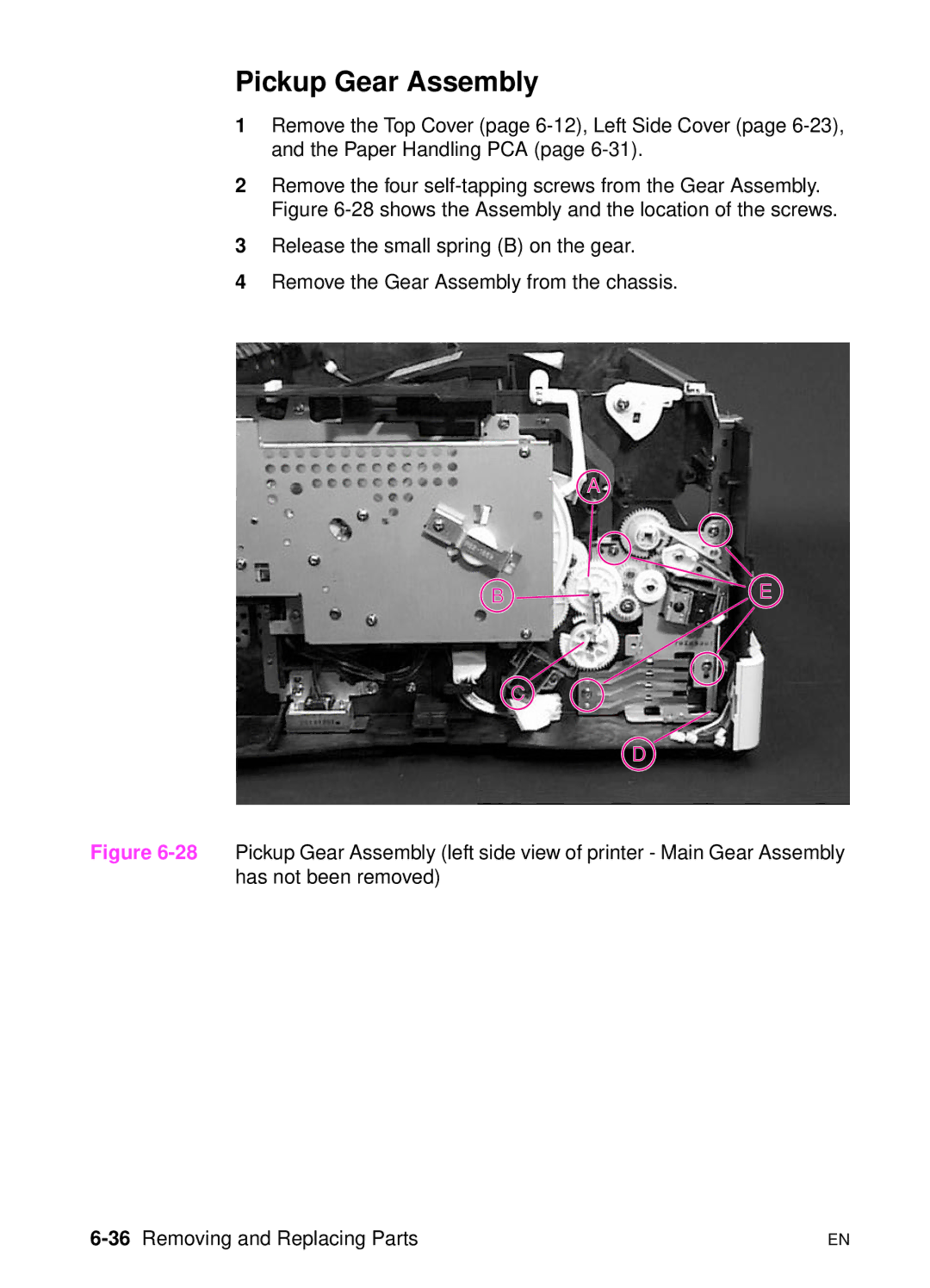
Pickup Gear Assembly
Tray 2 Shaft Gear to the Paper Feed Roller Assembly Gear
Tray 1 Pickup Solenoid
38Removing and Replacing Parts
30Fan right side view of printer
Fan
40Removing and Replacing Parts
Formatter Assembly
Tray 1 Roller
Tray 2 Roller
42Removing and Replacing Parts
34Paper Feed Roller Clutch left side view of printer
Paper Feed Roller Assembly
35Location of two common screws inside printer
44Removing and Replacing Parts
36Paper Feed Roller Assembly bottom view of printer
46Removing and Replacing Parts
DC Controller Board and Power Supply
37DC Controller Assembly rear view of printer
48Removing and Replacing Parts
38DC Controller Assembly long screws
39DC Controller Assembly
50Removing and Replacing Parts
Paper Feed Belt Assembly
41Paper Feed Belt Assembly removed
Tray 1 Shaft
52Removing and Replacing Parts
Must be installed on top of it
Tray 2 Shaft
54Removing and Replacing Parts
44Reassembly of Tray 2 Shaft
Reassembly Steps
Tray 1 Lift Plate
56Removing and Replacing Parts
46Tray 1 Separation Pad Removing Assemblies
Tray 1 Separation Pad
Paper Guide
58Removing and Replacing Parts
48Paper Path Detect Sensor
Paper Path Detect Sensor
Face Down Bin Full Sensor
60Removing and Replacing Parts
50Detail of Bin Full Sensor
62Removing and Replacing Parts
Power Connection
52Registration Assembly
Registration Assembly
64Removing and Replacing Parts
53Registration Assembly Clutch
54Upper Delivery Assembly rear left view of printer
Upper Delivery Assembly
66Removing and Replacing Parts
56Delivery Roller Components
Delivery Roller Removal
68Removing and Replacing Parts
58Laser Scanner Assembly top inside view of printer
Laser Scanner Assembly
Main Motor
70Removing and Replacing Parts
Toner Cartridge Guides
72Removing and Replacing Parts
Power Inlet Assembly
62Optional 500-sheet Tray top view
Optional 500-sheet Tray Disassembly
63500-sheet Tray top view with covers removed
74Removing and Replacing Parts
64Removing the Tray Indicator Assembly
Tray Indicator Assembly
76Removing and Replacing Parts
Left Front Corner Cover Installation
66Removing the Paper Size Spring Assembly
Paper Size Spring Assembly
Roller Removal
78Removing and Replacing Parts
Roller and Feed Roller
Feed Roller Removal
68Removing the Gear Assembly and PCA
Gear Assembly and PCA
80Removing and Replacing Parts
Power Connector
70Removing the Separation Roller
Separation Roller
82Removing and Replacing Parts
Troubleshooting
Major Steps for Troubleshooting
Troubleshooting Process
2Troubleshooting
Image Quality
4Troubleshooting
Troubleshooting Process Flow
Troubleshooting Process
6Troubleshooting
Troubleshooting the Printing System
Preliminary Operating Checks
Power on Defect or Blank Display ProblemAction
Power On
8Troubleshooting
No AC Power Cause
Action
No DC Power Cause Action
Engine Test Button Location
10Troubleshooting
Printing an Engine Test
Display
Event Log
12Troubleshooting
Event Log
Interpret the Event Log
14Troubleshooting
Display the Event Log
Print the Event Log
Left-most column
Event Log Explanation Recommended Message Action
16Troubleshooting
Printer Messages
Alphabetical Printer Messages Control Panel Message
Disk Device Failure
Cannot Duplex Rear BIN Open Check Input Device
Disk is Write Protected Flash Device Failure
18Troubleshooting
Input Device Condition xx.yy
Flash is Write Protected Initializing
20Troubleshooting
Do not Power OFF
Loading
Offline
Memory Full Stored Data Lost
System is Full
22Troubleshooting
RAM Disk Device Failure
RAM Disk File
Tray x Empty
Unsupported Size in Tray YY
24Troubleshooting
Wait for Printer to Reinitialize
USE Type Size INSTEAD?
Paper JAM
26Troubleshooting
Numerical Printer Messages Control Panel Message
Event Explanation Recommended Log Action Message
13.10 or Paper delay jam at paper
For 13.20
28Troubleshooting
Press GO to Continue
Buffer Overflow
Press GO to Continue Parallel I/O Buffer Overflow
Press GO to Continue Serial I/O Buffer Overflow
30Troubleshooting
Recommended Action
Printer Error
32Troubleshooting
Fuser Error
Printer Error
34Troubleshooting
Cycle Power to Continue
36Troubleshooting
69.x
38Troubleshooting
8x.yyyy
General Paper Path Troubleshooting Questions ProblemAction
General Paper Path Troubleshooting
40Troubleshooting
General Paper Path Troubleshooting Questions Problem Action
Paper Path Test
42Troubleshooting
Menu Map
Information Pages
44Troubleshooting
Configuration
46Troubleshooting
5Configuration
Verify installed options
Image Quality Checks Image Quality Checks Action
48Troubleshooting
Image Quality
Check the Toner Cartridge
EconoMode
Image Defects
50Troubleshooting
10. Black Possible Cause Action
Black Lines perpendicular path Possible Cause Action
10. Black
52Troubleshooting
11. Blank Possible Cause Action
54Troubleshooting
Empty weight = 1450 grams 51.5 oz
12. Blank Spots
11. Blank
12. Blank Spots Possible Cause Action
56Troubleshooting
13. Character Voids Possible Cause Action
14. Creases Possible Cause Action
15. Curl Possible Cause Action
58Troubleshooting
17. Distorted Image
16. Dirt on Back Possible Cause Action
18. Dropouts
60Troubleshooting
19. Faded Print/Bubbles Possible Cause Action
Family Paper Specifications Guide
19. Faded Print/Bubbles
62Troubleshooting
20. Gray Background Possible Cause Action
21. Horizontal Smudges Possible Cause Action
64Troubleshooting
23. Light Print, Dark Print, or Fade Possible Cause Action
22. Horizontal White Lines
23. Light Print, Dark Print, or Fade
66Troubleshooting
24. Loose Toner Possible Cause Action
25. Repetitive Defects Possible Cause Action
Examine and clean rollers in the paper path
26. Skew Possible Cause Action
68Troubleshooting
27. Toner Smear Possible Cause Action
Dirt in printer
28. Toner Specks Possible Cause Action
Paper SPEED=SLOW
70Troubleshooting
29. Vertical Black Lines
31. Vertical White Lines
30. Vertical Dots
Repetitive Defect Ruler
72Troubleshooting
6Repetitive Defect Ruler Troubleshooting the Printing System
74Troubleshooting
Image System Troubleshooting Half Self-Test Functional Check
Drum Rotation Functional Check
Communications Check
Interface Troubleshooting
EIO Troubleshooting
76Troubleshooting
7JetDirect Configuration Troubleshooting the Printing System
78Troubleshooting
JetDirect Configuration
Locations of Components
Reference Diagrams
9250-sheet Paper Feeder
80Troubleshooting
10250-sheet Paper Feeder Reference Diagrams
11Tray 2 Paper Path
82Troubleshooting
12500-sheet Paper Feeder Reference Diagrams
13500-sheet Paper Feeder
84Troubleshooting
Duplexing Unit
86Troubleshooting
Duplexing Unit
88Troubleshooting
Sensors and Signals
Page
90Troubleshooting
32. Sensors and Signals Name
TSW1
92Troubleshooting
19Location of Sensors and Switches
20Duplexer Sensors and Switches Reference Diagrams
94Troubleshooting
22Motors Duplexing unit Reference Diagrams
96Troubleshooting
Page
98Troubleshooting
26PCA Duplexing Unit Reference Diagrams
27Clutches and Solenoids
100Troubleshooting
28Clutches and Solenoids Duplexing Unit Reference Diagrams
102Troubleshooting
30Switches 500-sheet Paper Feeder Reference Diagrams
104Troubleshooting
31DC Controller Board Test Points and Switches
32250-sheet Paper Feeder Sensors Reference Diagrams
106Troubleshooting
DC Controller PCA Inputs and Outputs
33DC Controller PCA I/O 1 Reference Diagrams
34DC Controller PCA I/O 2
108Troubleshooting
35DC Controller PCA I/O 3 Reference Diagrams
36DC Controller PCA I/O 4
110Troubleshooting
Parts and Diagrams
Ordering Consumables
How To Use the Parts Lists and Diagrams
2Parts and Diagrams
Ordering Parts
Numbers
Accessories and Supplies Description Exchange No Product No
Accessories and Supplies
4Parts and Diagrams
Accessories and Supplies Description Exchange No. Product No
Replaceable Cables Description
Common Hardware and Replacement Cables
6Parts and Diagrams
Screws Used in the Printer Description
Illustrations and Parts Lists
8Parts and Diagrams
1Assembly Location Diagram
Illustrations and Parts Lists
2External Covers and Panels
10Parts and Diagrams
Illustrations and Parts Lists
12Parts and Diagrams
Top Cover Assembly Item No Quantity Description
Top Cover Assembly Item No Quantity Description
Internal Components 1 Item No. Part No Quantity Description
14Parts and Diagrams
Internal Components 1 Item No. Part No Quantity Description
5Internal Components 2
16Parts and Diagrams
Internal Components 2 Item No. Part No Quantity Description
6Internal Components 3
18Parts and Diagrams
Internal Components 3 Item No. Part No Quantity Description
7Internal Components 4
20Parts and Diagrams
Illustrations and Parts Lists
22Parts and Diagrams
8Upper Delivery Assembly
9Tray 2 Paper Pickup Roller Assembly
24Parts and Diagrams
10Paper Feed Belt Assembly
Illustrations and Parts Lists
26Parts and Diagrams
11Paper Feed Assembly
Illustrations and Parts Lists
28Parts and Diagrams
12Registration Roller Assembly
RG5-3524-000CN Registration Roller Assembly
Sheet Tray
30Parts and Diagrams
16 -sheet Tray Item No. Part No Quantity Description
32Parts and Diagrams
14Main Drive Assembly
Illustrations and Parts Lists
34Parts and Diagrams
15Pickup Drive Assembly
16PCA Assembly Locations
36Parts and Diagrams
17Printer Controller Assembly
21. Fuser Item No. Part No Quantity Description
Fuser
19500-sheet Feeder
38Parts and Diagrams
22 -sheet Feeder Item No. Part No Quantity Description
20500-sheet Feeder
40Parts and Diagrams
23 -sheet Feeder Item No. Part No Quantity Description
42Parts and Diagrams
Alphabetical Parts List
Description Part Number Table Number
Description Part Number Table Number
44Parts and Diagrams
70 on
46Parts and Diagrams
Part Number Description Table Number
Numerical Parts List
48Parts and Diagrams
110V RH2-5337-000CN 220V RG5-3517-000CN DC Controller 19 on
50Parts and Diagrams
Part Number Description Table Number
52Parts and Diagrams
Index
Index
Index
Index