Table
Symptom | Possible Problems | |
System shuts down. | • | Temperature too high |
| • | Loss of power |
Understanding Status LEDs
ERX Edge Routers
Actions
Note: The following actions apply to all of the possible problems.
1Verify that power connections are properly attached.
2 Verify that system is receiving power.
3 Check whether or not the LEDs are lit.
4 Run diagnostics on SRP and line modules.
5If system will not reset, contact Juniper Networks Customer Service.
Understanding Status LEDs
When you power up the system, it runs a series of tests for each module installed in the system. Refer to the tables in this section to understand normal and abnormal LED activity. For troubleshooting information, see Table
LED Identification
The system’s modules have two sets of status LEDs. The top set indicates generic router and module status. The bottom set indicates
The number against the port status LED on a line module corresponds to the number of the port on the I/O module. Some line modules have more port status LEDs than the number of ports on the I/O module. In these cases, only the LEDs for the corresponding ports on the I/O modules are active.
For example, an OCx/STMx line module can pair with either an
Table
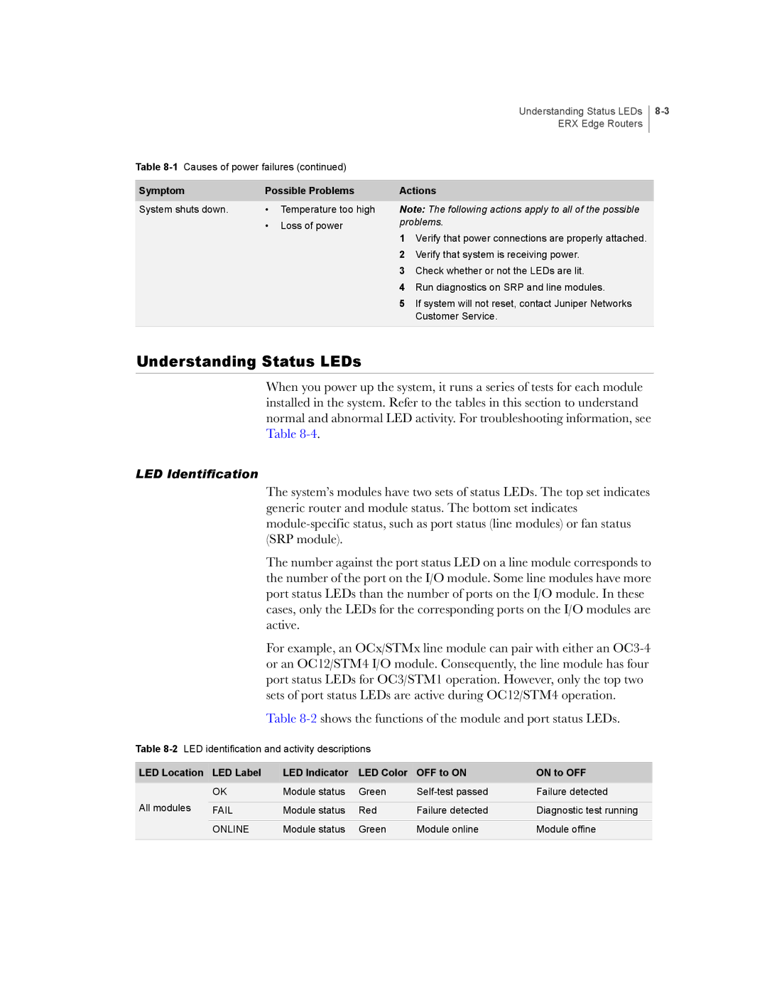
Table
LED Location | LED Label | LED Indicator | LED Color | OFF to ON | ON to OFF |
| OK | Module status | Green | Failure detected | |
All modules |
|
|
|
|
|
FAIL | Module status | Red | Failure detected | Diagnostic test running | |
|
|
|
|
|
|
| ONLINE | Module status | Green | Module online | Module offine |
|
|
|
|
|
|