APPENDIX C Cable Pinouts
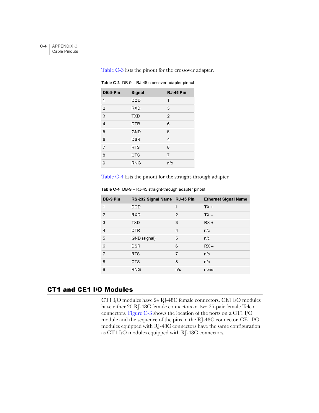
Table C-3 lists the pinout for the crossover adapter.
Table
| Signal |
|
1 | DCD | 1 |
|
|
|
2 | RXD | 3 |
|
|
|
3 | TXD | 2 |
|
|
|
4 | DTR | 6 |
|
|
|
5 | GND | 5 |
|
|
|
6 | DSR | 4 |
|
|
|
7 | RTS | 8 |
|
|
|
8 | CTS | 7 |
|
|
|
9 | RNG | n/c |
|
|
|
Table C-4 lists the pinout for the straight-through adapter.
Table
|
|
| Ethernet Signal Name |
1 | DCD | 1 | TX + |
|
|
|
|
2 | RXD | 2 | TX – |
|
|
|
|
3 | TXD | 3 | RX + |
|
|
|
|
4 | DTR | 4 | n/c |
|
|
|
|
5 | GND (signal) | 5 | n/c |
|
|
|
|
6 | DSR | 6 | RX – |
|
|
|
|
7 | RTS | 7 | n/c |
|
|
|
|
8 | CTS | 8 | n/c |
|
|
|
|
9 | RNG | n/c | none |
|
|
|
|
CT1 and CE1 I/O Modules
CT1 I/O modules have 24